1Overview
The 7000 Series is a fully integrated cross-correlation signal source analyzer that offers an indispensable set of measurement functions for evaluating signal sources from VHF to microwave frequencies, including crystal oscillators, PLL synthesizers, clocks, phase-locked or free-running VCOs, DROs, SAW and YIG oscillators, and more. It measures signals from 1 MHz to 7, 26, or 40 GHz depending on model.
The instrument is a two-channel cross-correlation system with two internal tunable reference sources, and it also supports measurements with externally fed references. Cross-correlation between the two channels averages out the analyzer's own noise, so sensitivity reaches down to -190 dBc/Hz. The offset analysis range spans 0.01 Hz to 100 MHz.
Beyond absolute phase noise, the 7000 Series supports residual (additive) phase noise, pulsed absolute and residual phase noise, amplitude noise, two-channel 100 MHz FFT analysis, transient measurements (frequency, phase, amplitude versus time), spectrum analysis, and a frequency-counter and power-meter function. Two programmable low-noise DC supplies (up to 15 V, 550 mA per channel) and three low-noise tuning voltages (-5 to +20 V) make it a complete VCO characterization bench.
It is a compact, powerful instrument available with LAN (VXI-11), USBTMC, or optional GPIB interfaces. A platform-independent graphical user interface (GUI), an API library, and a full SCPI command set are provided. Operated from an external 24 V DC supply, it consumes less than 70 W.
Specification conditions. Unless otherwise stated, specifications describe warranted performance for 23 ±5 °C after a 30-minute warm-up. Min/Max values are guaranteed by design and/or production tested and include guard-bands. Typical values are expected mean values, not warranted performance.
2Model Selection
Three base models share the same chassis, GUI, and option set and differ only in top frequency. All three are two-channel cross-correlation analyzers that start at 1 MHz with internal references.
| Model | Frequency range (internal ref.) | RF input connector | Description |
|---|---|---|---|
| 7070 | 1 MHz to 7 GHz | SMA female | 7 GHz signal source analyzer |
| 7300 | 1 MHz to 26 GHz | SMA female | 26 GHz signal source analyzer |
| 7340 | 1 MHz to 40 GHz | K (2.92 mm) female | 40 GHz signal source analyzer |
With external references the range is 5 MHz to 7 GHz on the 7070 and 5 MHz to 18 GHz on the 7300 and 7340. The internal-reference top frequency (FMAX) referenced throughout this datasheet is 7, 26, or 40 GHz for the 7070, 7300, and 7340 respectively.
3Key Features
- All-in-one compact measurement system covering absolute, residual, pulsed, and AM phase noise plus transient, spectrum, VCO, and time-stability analysis.
- Measurements down to -190 dBc/Hz using two-channel cross-correlation.
- Offset range from 0.01 Hz to 100 MHz.
- Highest flexibility and dynamic range through selectable internal or external references.
- Two programmable low-noise DC power supplies (up to 15 V, 550 mA per channel) and three low-noise DUT tuning voltages.
- Powerful GUI and programming interface with API library and SCPI command set.
- External battery pack option for portable and field use.
4Measurement Modes
The 7000 Series consolidates a full suite of source-characterization measurements into one instrument. Standard modes ship with every unit; the remaining modes are enabled by software options (see Options & Accessories).
Absolute phase noise (CW)
Standard mode. Reports SSB phase noise [dBc/Hz], spurious noise [dBc], integrated RMS phase-noise deviation [deg, rad], time jitter [s], and residual FM/PM [Hz RMS] from 1 MHz to 40 GHz using internal or external references.
Residual (additive) phase noise
Measures the added phase noise of two-port devices such as amplifiers, transmitters, dividers, and mixers under CW (Option APN) or pulsed (Option APN + PULSE) drive.
Pulsed phase noise
Absolute phase noise on pulsed RF carriers (Option PULSE), with Option NPS extending coverage to narrow pulses and low duty cycles. Burst-mode phase noise (Option PULSE + Option BURST) analyzes single bursts as short as 10 µs.
Amplitude, baseband, transient, spectrum, and time stability
Absolute amplitude (AM) noise, baseband noise-spectrum analysis on two rear BNC inputs, transient frequency/phase/amplitude versus time (Option TRAN), spectrum monitoring (Option SPEC), and Allan-deviation time-stability analysis with no dead time (Option TSTAB).
VCO characterization, frequency counter, and power detector
Option VCO turns the instrument into a full VCO bench, sweeping tuning voltage while logging frequency, KVCO tuning sensitivity, pushing, output power, supply current, and phase noise. A built-in frequency counter and RF power detector round out the standard feature set.
5Specifications
Absolute phase noise measurement, 1 MHz to 40 GHz (continuous waveform)
Measurement parameters: SSB phase noise [dBc/Hz], spurious noise [dBc], integrated RMS phase-noise deviation [deg, rad], time jitter [s], residual FM/PM [Hz RMS].
| Parameter | Min | Typical | Max | Note |
|---|---|---|---|---|
| RF frequency range (internal references) | FMIN to FMAX | |||
| 7070 | 1 MHz | 7 GHz | ||
| 7300 | 1 MHz | 26 GHz | ||
| 7340 | 1 MHz | 40 GHz | ||
| RF frequency range (external references) | ||||
| 7070 | 5 MHz | 7 GHz | ||
| 7300 / 7340 | 5 MHz | 18 GHz | ||
| Input power range | Damage level +26 dBm. See RF sensitivity plots. | |||
| < 18 GHz | -15 dBm | +20 dBm | ||
| 18 GHz to 30 GHz | -15 dBm | +23 dBm | ||
| > 30 GHz | -5 dBm | +23 dBm | ||
| Input impedance | 50 Ω | AC coupled, 10 V DC max | ||
| VSWR | 2 | |||
| Offset analysis range | ||||
| fC > 150 MHz | 0.01 Hz | 100 MHz | ||
| fC < 150 MHz | 0.01 Hz | > 25% of fC | ||
| Resolution (PPD) | 200 | 200 | 1600 | RBW adjustable (x1/x2/x4/x8); PPD (points per decade) can be lower for the lowest decade of measurement |
| Measurement accuracy | ||||
| Offset < 10 Hz | ±4 dB | |||
| Offset 10 Hz to 1 kHz | ±3 dB | |||
| Offset 1 kHz to 100 MHz | ±2 dB | |||
| Phase noise sensitivity | See plots and sensitivity tables | |||
| Spurious levels | ||||
| Internal references | -90 dBc | |||
| External references | -85 dBc | |||
| Measurement time | See table “Phase noise measurement time” | |||
| Trigger | Single, continuous, manual, bus | |||
| Internal references | Cross-correlation | |||
| Frequency range | 1 MHz | FMAX | ||
| RF tracking range | ±1 ppm | Option LN | ||
| RF tracking range | ±10 ppm | Standard | ||
| RF tracking range | ±1000 ppm | High drift mode | ||
| External references | Single channel / cross-corr. | |||
| Frequency range, 7070 | 5 MHz | 7 GHz | ||
| Frequency range, 7300 / 7340 | 5 MHz | 18 GHz | ||
| RF input power range | 0 dBm | +23 dBm | Damage level +26 dBm | |
| Reference input level, < 1.3 GHz | +10 dBm | +15 dBm | +21 dBm | Lower input ports |
| Reference input level, > 1.3 GHz | +13 dBm | +15 dBm | +21 dBm | Upper input ports |
| Tuning voltage range | -5 V | +20 V | User adjustable | |
| Tuning output current | 20 mA |
Absolute phase noise measurement – pulsed (Option PULSE / NPS)
| Parameter | Min | Typical | Max | Note |
|---|---|---|---|---|
| RF frequency range | ||||
| 7070 | 30 MHz | 7 GHz | ||
| 7300 | 30 MHz | 26 GHz | ||
| 7340 | 30 MHz | 40 GHz | ||
| RF input power range | +5 dBm | +20 dBm | No power measurement | |
| Input parameters | ||||
| Pulse rate (PRF) | 300 Hz | 2 MHz | ||
| Pulse width | 1 µs | 2 ms | Option PULSE | |
| Pulse width | 50 ns | 2 ms | Option NPS | |
| Duty cycle | 2% | 60% | Option PULSE | |
| Duty cycle | 0.1% | 60% | Option NPS | |
| Offset analysis range | 0.01 Hz | PRF | ||
| Measurement accuracy | ||||
| Offset < 10 Hz | ±4 dB | |||
| Offset 10 Hz to 1 kHz | ±3 dB | |||
| Offset 1 kHz to 100 MHz | ±2 dB | |||
| Measurement time | See table “Measurement time” |
Residual (additive) phase noise – CW (Option APN) and pulsed (Option APN + PULSE)
Measurement parameters: SSB phase noise [dBc/Hz], spurious noise [dBc], integrated RMS phase-noise deviation [deg, rad], time jitter [s], residual FM/PM [Hz RMS].
| Parameter | Min | Typical | Max | Note |
|---|---|---|---|---|
| RF frequency range | ||||
| 7070 | 10 MHz | 7 GHz | ||
| 7300 / 7340 | 10 MHz | 18 GHz | ||
| RF input power range | ||||
| RF port | +3 dBm | +23 dBm | ||
| REF ports | +13 dBm | +20 dBm | ||
| LO output power range | +17 dBm | +23 dBm | Option LO | |
| Offset analysis range | 0.01 Hz | 100 MHz | ||
| Measurement accuracy | ||||
| Offset < 1 kHz | ±3 dB | |||
| Offset > 1 kHz | ±2 dB | |||
| Additive phase noise sensitivity | See sensitivity table |
Transient analysis (Option TRAN)
Measurement parameters: wideband mode (WB) – frequency [Hz]; narrowband mode (NB) – frequency [Hz], RF power [dB], phase [deg].
| Parameter | Min | Typical | Max | Note |
|---|---|---|---|---|
| RF frequency bands (WB) | ||||
| Band 1 | 5 MHz | 100 MHz | ||
| Band 2 | 20 MHz | 400 MHz | ||
| Band 3 | 80 MHz | 1.6 GHz | ||
| Band 4 | 320 MHz | 3 GHz | ||
| Band 5 | 1.3 GHz | 26 GHz | ||
| Band 6 | 5.2 GHz | FMAX | ||
| Measurement spans | ||||
| Wideband mode (WB) | Bands 1-6 | |||
| Narrowband mode (NB) | 200 kHz | 80 MHz | 200 kHz, 1.25 MHz, 80 MHz | |
| Frequency resolution | See resolution tables | |||
| Time span | 10 µs | 1 min | ||
| Time resolution | 16 ns | 50 ms | ||
| Trigger mode | Single, continuous, internal (WB video or NB video), external |
Burst mode phase noise measurement (Option PULSE + Option BURST)
| Parameter | Min | Typical | Max | Note |
|---|---|---|---|---|
| RF frequency range | 5 MHz | FMAX | ||
| Offset analysis range | 1 / T | 30 MHz | ||
| Time span (T) | 10 µs | 1 min | ||
| Phase noise sensitivity | Single channel, f = 1 GHz | |||
| 1 kHz | -120 dBc/Hz | |||
| 10 kHz | -128 dBc/Hz | |||
| 100 kHz | -131 dBc/Hz | |||
| 1 MHz | -131 dBc/Hz | |||
| 10 MHz | -147 dBc/Hz |
Absolute amplitude noise measurement (Option AM)
| Parameter | Min | Typical | Max | Note |
|---|---|---|---|---|
| RF frequency range | ||||
| 7070 | 5 MHz | 7 GHz | ||
| 7300 | 5 MHz | 26 GHz | ||
| 7340 | 5 MHz | 40 GHz | ||
| RF input power range | ||||
| 5 MHz to 10 GHz | -20 dBm | +20 dBm | ||
| 10 GHz to 40 GHz | -10 dBm | +20 dBm | ||
| Offset analysis range | 0.1 Hz | 40 MHz | ||
| Measurement uncertainty | ±2 dB | |||
| AM noise sensitivity (1 corr.) | 1 GHz, Pin = -10 dBm to +20 dBm | |||
| 1 Hz | -100 dBc/Hz | |||
| 10 Hz | -115 dBc/Hz | |||
| 100 Hz | -135 dBc/Hz | |||
| 1 kHz | -145 dBc/Hz | |||
| 10 kHz | -155 dBc/Hz | |||
| > 100 kHz | -160 dBc/Hz |
Baseband noise analysis
Input connectors: 2 BNC female (rear panel), AC coupled. Measurement parameter: noise spectrum [nV/√Hz].
| Parameter | Min | Typical | Max | Note |
|---|---|---|---|---|
| Frequency input range | 1 Hz | 100 MHz | ||
| DC voltage input range | -12 V | +12 V | ||
| Input impedance | 1 kΩ | DC | ||
| AC voltage range | +10 dBm | |||
| Input noise density (1 correlation), 10 kHz | < 3 nV/√Hz | |||
| Trigger | Single, continuous, manual, bus |
Time stability measurement (Option TSTAB)
Measurement parameter: ADEV (no dead time).
| Parameter | Min | Typical | Max | Note |
|---|---|---|---|---|
| Measurement time | 1 s | 10 days | ||
| Resolution bandwidth (RBW) | 1 Hz | 100 Hz | 100 Hz | Setable to 1 Hz, 100 Hz |
| ADEV sensitivity | With RBW 100 Hz | |||
| τ = 1 s | 5e-13 | |||
| τ = 100 s | 1e-13 |
Spectrum monitoring (Option SPEC)
Measurement parameter: spectral noise density [dBm].
| Parameter | Min | Typical | Max | Note |
|---|---|---|---|---|
| RF frequency range | ||||
| 7070 | 5 MHz | 7 GHz | ||
| 7300 | 5 MHz | 26 GHz | ||
| 7340 | 5 MHz | 40 GHz | ||
| RBW | 5.8 Hz | 58 kHz | ||
| Measurement uncertainty | ||||
| Absolute | ±3 dB | |||
| Relative | ±1 dB | |||
| Noise floor | ||||
| 10 MHz to 4 GHz | -95 dBm/Hz | |||
| 4 GHz to 18 GHz | -90 dBm/Hz | |||
| 18 GHz to 40 GHz | -80 dBm/Hz | |||
| Spurious (SFDR) | Spurious free dynamic range | |||
| 10 MHz to 4 GHz | -70 dBc | |||
| 4 GHz to 18 GHz | -60 dBc | |||
| 18 GHz to 40 GHz | -55 dBc | |||
| Trigger | Continuous |
VCO characterization (Option VCO)
Measurement parameters: frequency [Hz], KVCO tuning sensitivity (Δf/ΔVc) [Hz/V], frequency pushing [Hz/V], RF power level [dBm], DC supply current [mA], SSB phase noise [dBc/Hz].
| Parameter | Min | Typical | Max | Note |
|---|---|---|---|---|
| Sweep parameters | ||||
| DC supply voltage | 0 V | 15 V | Adjustable | |
| DC supply current | 550 mA | |||
| Tuning voltage | -5 V | 20 V | Adjustable | |
| Tuning current | 20 mA | |||
| RF frequency range | 5 MHz | FMAX | ||
| Uncertainty | 0.5 ppm | |||
| RF input power range | -5 dBm | +20 dBm | ||
| Uncertainty | 0.5 dB | 2 dB | ||
| DC supply current | 0 mA | 550 mA | ||
| Uncertainty | 1% | |||
| Output settling time | 20 ms | |||
| Measurement speed | 70 ms / point | Frequency, KVCO, pushing, supply current, and power |
Frequency counter
| Parameter | Min | Typical | Max | Note |
|---|---|---|---|---|
| RF frequency range | 1 MHz | FMAX | ||
| Absolute accuracy | 300 ppb | Or accuracy of external reference | ||
| Sensitivity | See plot “Typical RF sensitivity plot” |
Power detector
| Parameter | Min | Typical | Max | Note |
|---|---|---|---|---|
| RF frequency range | ||||
| 7070, 7300 | 5 MHz | FMAX | ||
| 7340 | 5 MHz | 40 GHz | ||
| Absolute accuracy | ±1 dB | ±2.5 dB | ||
| Power range | -10 dBm | +13 dBm |
Tuning voltage and dual power supply
| Parameter | Min | Typical | Max | Note |
|---|---|---|---|---|
| DUT tuning | BNC front panel output | |||
| DC voltage range | -5 V | +22 V | ||
| Setting resolution | 1 mV | |||
| Setting uncertainty | ±2 mV | |||
| Noise level | < 2 nVrms/√Hz | > 2 kHz | ||
| DC current range | 0 mA | 20 mA | ||
| DC power supplies | BNC rear panel output (channel 1 & 2) | |||
| DC voltage range | 0 V | 15 V | ||
| Setting resolution | 10 mV | |||
| Setting accuracy | ±10 mV | |||
| Noise level | < 10 nVrms/√Hz | > 20 kHz | ||
| Output resistance | < 0.5 Ω | |||
| DC current measurement range | 0 mA | 550 mA | Per channel | |
| Resolution | 100 µA |
LO output (Option LO)
| Parameter | Min | Typical | Max | Note |
|---|---|---|---|---|
| Use: additive phase noise | ||||
| Frequency range | 0 GHz | 18 GHz | ||
| Frequency resolution | 1 Hz | |||
| Power level | 14 dBm | 17.5 dBm | 20 dBm | |
| Use: LO for downconversion | ||||
| Frequency range | 2 GHz | 20 GHz | ||
| Frequency resolution | 0.5 GHz | |||
| Power level | 14 dBm | 17.5 dBm | 21 dBm |
Phase noise measurement time
Total measurement time consists of setup time and transfer time plus the number of performed correlations times the time per correlation. The times below are normalized to one correlation for nominal RBW settings, and measurement times greater than 2 seconds.
| Measurement range | Time per correlation [s] | Default number of points (settable) |
|---|---|---|
| 0.1 Hz to 100 MHz | 80 | 250 per decade |
| 1 Hz to 100 MHz | 8 | 250 per decade |
| 10 Hz to 100 MHz | 0.8 | 250 per decade |
| 100 Hz to 100 MHz | 0.1 | 250 per decade |
| 1 kHz to 100 MHz | 0.01 | 250 per decade |
| 10 kHz to 100 MHz | < 0.004 | 250 per decade |
Transient analysis – frequency resolution vs. time resolution
Frequency measurement uncertainty is ± (resolution + time-base uncertainty). Tabulated resolutions are measured with the 7000 Series and the DUT locked to the same 10 MHz reference at an input level of 0 dBm.
Wideband (residual FM, 5% video bandwidth, typical) — frequency resolution [Hz]
| Frequency band | 16 ns | 128 ns | 500 ns | 1 µs | ≥10 µs |
|---|---|---|---|---|---|
| 5 MHz to 100 MHz | 3 k | 100 | 30 | 15 | 10 |
| 20 MHz to 400 MHz | 5 k | 700 | 200 | 100 | 20 |
| 80 MHz to 1.6 GHz | 10 k | 1 k | 200 | 100 | 50 |
| 320 MHz to 3 GHz | 30 k | 1.5 k | 300 | 150 | 150 |
| 1.3 GHz to 26 GHz | 100 k | 6 k | 2 k | 1 k | 1 k |
| 5.2 GHz to FMAX | 500 k | 20 k | 4 k | 2 k | 2 k |
Narrowband (residual FM, 80 MHz span, 5% video bandwidth, typical) — frequency resolution [Hz]
| Frequency range | 16 ns | 128 ns | 500 ns | 1 µs | 10 µs | ≥20 µs |
|---|---|---|---|---|---|---|
| < 200 MHz | 1.5 k | 50 | 10 | 4 | 4 | 4 |
| < 800 MHz | 2.5 k | 150 | 15 | 10 | 4 | 4 |
| < 2 GHz | 2.5 k | 500 | 20 | 10 | 4 | 4 |
| < 20 GHz | 30 k | 4 k | 150 | 70 | 20 | 7 |
| > 20 GHz | 50 k | 4 k | 400 | 150 | 50 | 15 |
Narrowband (residual FM, 1.25 MHz span, no video bandwidth, typical) — frequency resolution [Hz]
| Frequency range | 256 ns | 500 ns | 1 µs | 10 µs | ≥20 µs |
|---|---|---|---|---|---|
| < 200 MHz | 60 | 30 | 15 | 1.5 | 0.5 |
| < 800 MHz | 70 | 30 | 15 | 1.5 | 1.5 |
| < 2 GHz | 100 | 40 | 15 | 3 | 1.5 |
| < 20 GHz | 1 k | 300 | 150 | 30 | 15 |
| > 20 GHz | 3 k | 1 k | 400 | 60 | 30 |
Narrowband (residual FM, 200 kHz span, no video bandwidth, typical) — frequency resolution [Hz]
| Frequency range | 1 µs | 10 µs | ≥20 µs |
|---|---|---|---|
| < 200 MHz | 1 | 0.5 | 0.3 |
| < 800 MHz | 1.5 | 0.5 | 0.3 |
| < 2 GHz | 3 | 1 | 0.4 |
| < 20 GHz | 20 | 10 | 3 |
| > 20 GHz | 50 | 20 | 10 |
General characteristics
| Parameter | Specification |
|---|---|
| Remote programming interfaces | Ethernet 100BaseT LAN interface; USB 2.0 device; GPIB (IEEE-488.2, 1987) with listen and talk (Option GPIB); control language SCPI version 1999.0 |
| Power requirements | 24 V ± 3.0 VDC; 70 W maximum |
| Mains adapter supplied | 100-240 VAC in / 24 V 4.0 A DC out |
| Environmental | Levels similar to MIL-PRF-28800F Class 3/4 |
| Safety / EMC (CE) | Safety and EMC comply with applicable Safety and EMC regulations and directives |
| Weight | ≤ 10.0 kg (21 lbs) net |
| Dimensions, incl. rubber | 154 mm H x 467.5 mm W x 342 mm L (6.1 in x 18.4 in x 13.5 in) |
| Dimensions, with handle | 154 mm H x 520 mm W x 342 mm L (6.1 in x 20.5 in x 13.5 in) |
| Handle | Radius 230 mm (9 in); turns 360° in 30° steps |
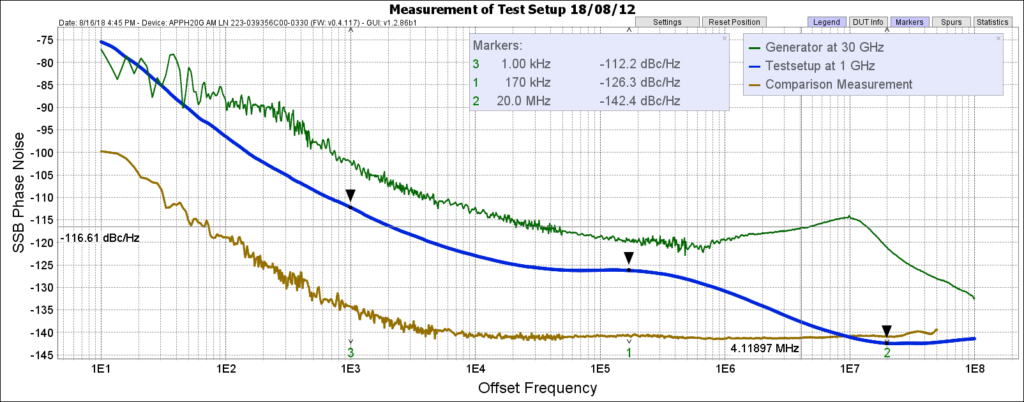
6Cross-Correlation & Sensitivity
Cross-correlation is how the 7000 Series reaches its floor. Both channels measure the same device against independent internal references, and averaging the two channels cancels the analyzer's own uncorrelated noise. Each additional decade of correlations lowers the displayed noise floor: roughly 5 dB for 10, 10 dB for 100, and 15 dB for 1000 correlations. Thermal noise (-177 dBm/Hz PM) can also limit the measurement at low input power (below 10 dBm).
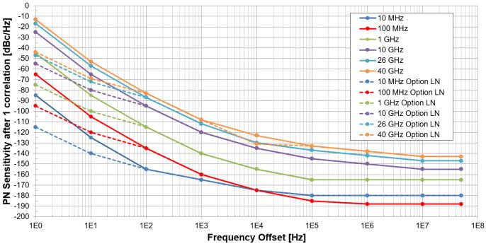
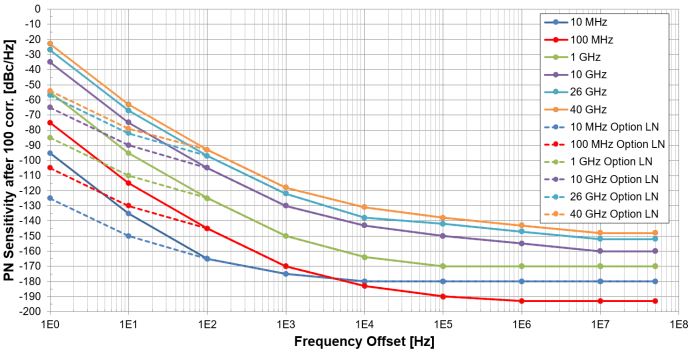
Absolute phase noise sensitivity – internal references (standard)
SSB phase noise floor [dBc/Hz] versus carrier frequency and offset. Test conditions: carrier power ≥ 5 dBm; after one correlation.
| Carrier | 1 Hz | 10 Hz | 100 Hz | 1 kHz | 10 kHz | 100 kHz | 1 MHz |
|---|---|---|---|---|---|---|---|
| 10 MHz | -85 | -125 | -155 | -165 | -172 | -175 | -175 |
| 100 MHz | -65 | -105 | -135 | -160 | -172 | -178 | -178 |
| 1 GHz | -45 | -85 | -115 | -140 | -155 | -160 | -160 |
| 3 GHz | -35 | -75 | -105 | -130 | -145 | -150 | -155 |
| 10 GHz | -25 | -65 | -95 | -120 | -135 | -140 | -145 |
| 25 GHz | -15 | -55 | -85 | -110 | -130 | -135 | -140 |
| 40 GHz | -13 | -53 | -83 | -108 | -123 | -133 | -138 |
Absolute phase noise sensitivity – internal references (with Option LN)
Test conditions: carrier power ≥ 5 dBm; after one correlation. Option LN ultra-low-noise internal sources improve close-in sensitivity substantially.
| Carrier | 1 Hz | 10 Hz | 100 Hz | 1 kHz | 10 kHz | 100 kHz | 1 MHz |
|---|---|---|---|---|---|---|---|
| 10 MHz | -115 | -140 | -155 | -165 | -172 | -175 | -175 |
| 100 MHz | -95 | -120 | -135 | -160 | -172 | -178 | -178 |
| 1 GHz | -75 | -100 | -115 | -140 | -155 | -160 | -160 |
| 3 GHz | -65 | -90 | -105 | -130 | -145 | -150 | -155 |
| 10 GHz | -55 | -80 | -95 | -120 | -135 | -140 | -145 |
| 25 GHz | -45 | -70 | -85 | -110 | -130 | -135 | -140 |
| 40 GHz | -44 | -68 | -83 | -108 | -123 | -133 | -138 |
Absolute phase noise sensitivity – external references
Test conditions: carrier power ≥ 5 dBm; after one correlation.
| Carrier | 1 Hz | 10 Hz | 100 Hz | 1 kHz | 10 kHz | 100 kHz | 1 MHz |
|---|---|---|---|---|---|---|---|
| 10 MHz | -135 | -150 | -155 | -170 | -175 | -175 | -175 |
| 100 MHz | -120 | -130 | -140 | -170 | -178 | -178 | -178 |
| 1 GHz | -100 | -110 | -125 | -155 | -170 | -170 | -170 |
| 3 GHz | -95 | -110 | -125 | -155 | -170 | -170 | -170 |
| 10 GHz | -90 | -110 | -120 | -145 | -155 | -155 | -155 |
| 18 GHz | -85 | -105 | -115 | -130 | -140 | -145 | -145 |
Additive phase noise sensitivity – single channel
Test conditions: RF carrier power ≥ 10 dBm; REF ≥ 13 dBm. Two-channel cross-correlation can improve the noise floor by 5 dB per 10x correlations.
| Frequency | 1 Hz | 10 Hz | 100 Hz | 1 kHz | 10 kHz | 100 kHz | 1 MHz |
|---|---|---|---|---|---|---|---|
| 10 MHz ≤ f ≤ 1 GHz | -130 | -140 | -150 | -160 | -170 | -170 | -170 |
| 1 GHz ≤ f ≤ 4 GHz | -130 | -140 | -150 | -160 | -170 | -170 | -170 |
| 4 GHz ≤ f ≤ 16 GHz | -115 | -125 | -135 | -145 | -150 | -155 | -160 |
Typical noise floor. After more than 1000 correlations the instrument reaches roughly -190 to -200 dBc/Hz at high offsets, for example at 100 MHz and 1 GHz carriers. Actual floor depends on carrier frequency, input power, and the number of correlations performed.
7Options & Accessories
Every 7000 Series unit is field-upgradable. Standard units include absolute phase noise, baseband noise, spectrum, frequency counter, and power detector; the options below unlock the remaining modes.
| Option | Function |
|---|---|
| LN | Ultra-low-noise internal sources |
| PULSE | Pulsed signal measurement |
| NPS | Pulsed signal measurement for narrow pulses and low duty cycles |
| TRAN | Transient analysis |
| BURST | Burst mode phase noise measurement (requires Option PULSE) |
| AM | Amplitude noise measurement |
| APN | Additive phase noise measurement |
| LO | Access to internal reference for residual phase noise measurement (requires Option APN) |
| TSTAB | Time stability analysis |
| VCO | VCO characterization |
| SPEC | Spectrum monitoring |
| GPIB | GPIB interface |
| RM | Rack mount chassis |
Accessories
| Accessory | Description |
|---|---|
| APNS | Traceable AM / PN noise standard, flange-mount module |
| PS06 | Mechanical phase shifter 1 – 6 GHz for additive phase noise measurements |
| PS18 | Mechanical phase shifter 6 – 18 GHz for additive phase noise measurements |
8Software & Remote Control
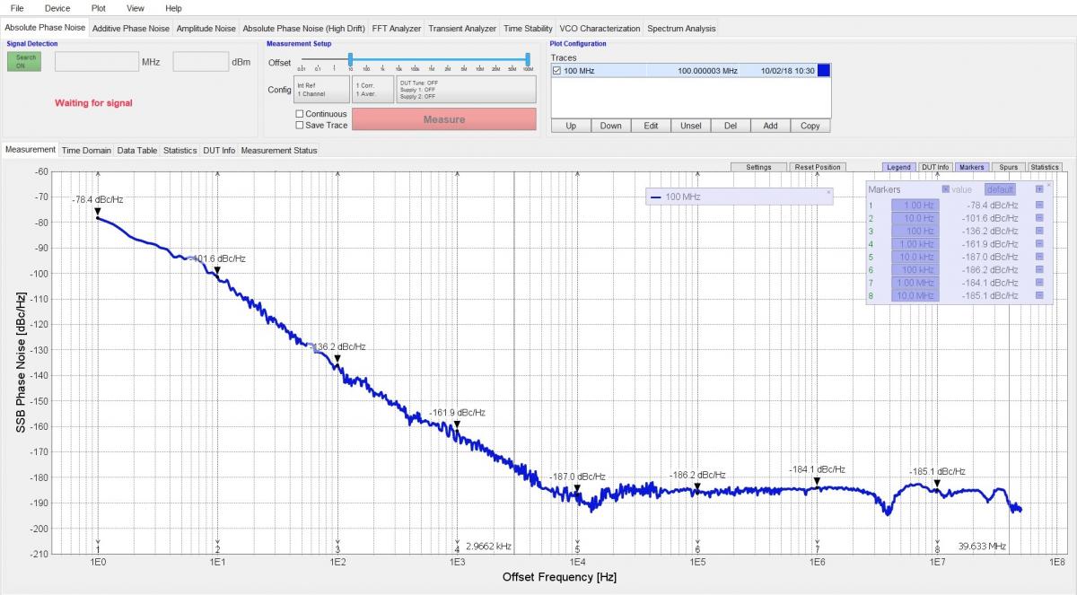
The 7000 Series runs a platform-independent graphical user interface based on the Windows operating system, with one tab per measurement mode (absolute phase noise, additive phase noise, amplitude noise, high-drift phase noise, FFT analyzer, transient analyzer, time stability, VCO characterization, and spectrum monitoring). An API library and a full SCPI command set (SCPI version 1999.0) support automated production and bench control.
Data processing capabilities
| Function | Description |
|---|---|
| Display functions | Phase noise, time domain, data table, residual, statistics |
| Data traces | Display current measurement and/or multiple memory data (up to 16 traces) |
| Title | Add a customized title to each measurement window |
| Auto-scale | Automatically selects scale resolution and reference value to vertically center the trace |
| Statistics | Calculates and displays mean, standard deviation, and peak-to-peak deviation of the trace |
| Marker functions | 16 independent markers |
Remote programming interfaces
- LAN: Ethernet 100BaseT, VXI-11.
- USB: USB 2.0 device, USBTMC.
- GPIB (Option GPIB): IEEE-488.2, 1987, with listen and talk.
- Control language: SCPI version 1999.0.
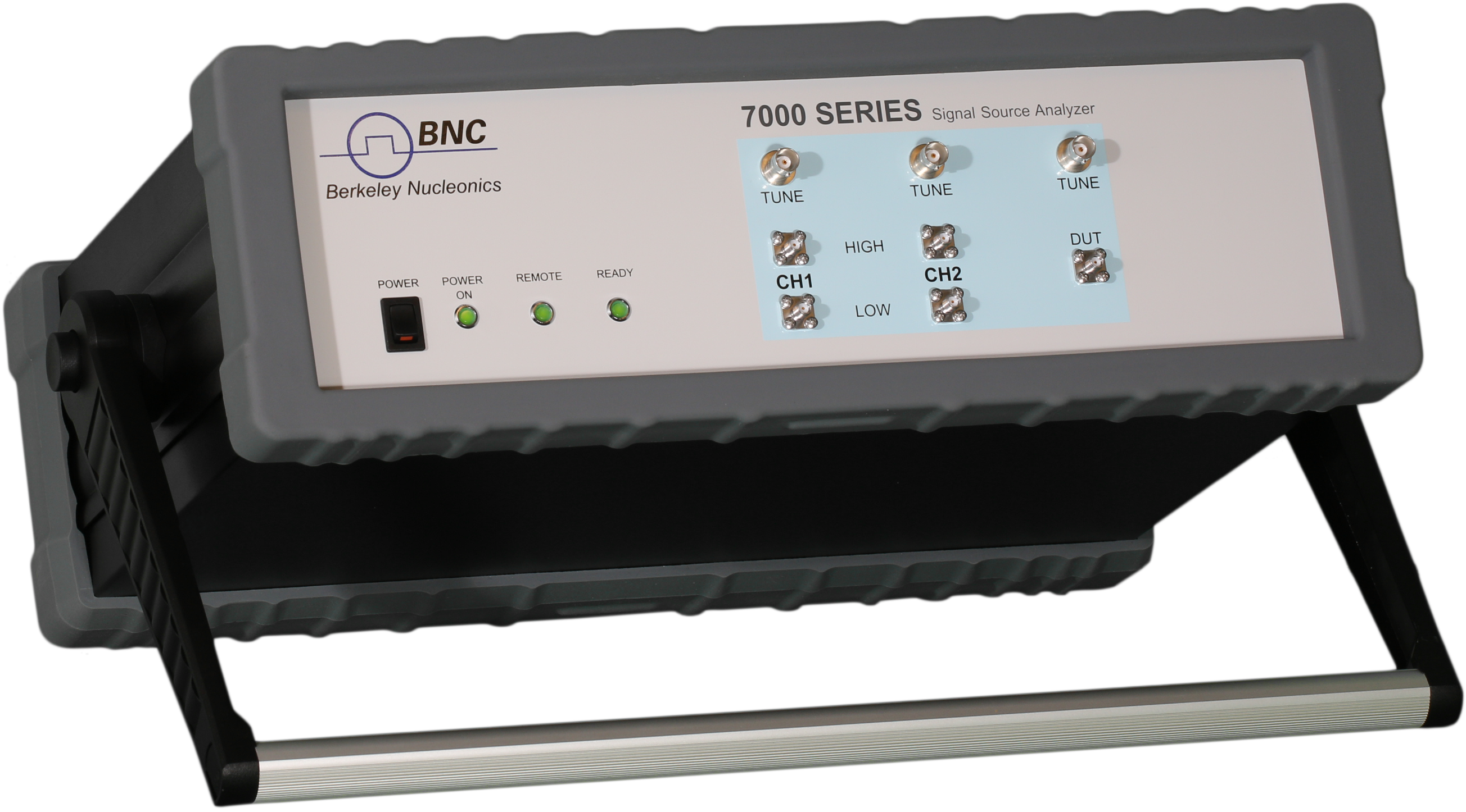
9Connectors
The following connector list transcribes the front- and rear-panel callouts from the datasheet. Panel photographs are shown in the source PDF.
Front panel
| Group | Connector | Type |
|---|---|---|
| RF inputs | RF IN | SMA female (7070 / 7300); K female (7340) |
| RF inputs | REF1 IN HIGH/LOW, REF2 IN HIGH/LOW | SMA female |
| DC outputs | REF1 TUNE, REF2 TUNE | BNC female |
| Operation | Switch I/O | DC power switch |
| Operation | POWER, READY, REMOTE | Status LED |
Rear panel
| Group | Connector | Type |
|---|---|---|
| HF/VHF/AUX inputs | BASEBAND CH1, BASEBAND CH2 | BNC female |
| HF/VHF/AUX inputs | REF IN 10 MHz | BNC female |
| HF/VHF/AUX inputs | EXT TRIG | BNC female |
| DC outputs | DC SUPPLY CH1, DC SUPPLY CH2 | BNC female |
| Operation | LAN | RJ-45 |
| Operation | USB B | USB 2.0 device |
| Operation | DC 24V | DC power plug (24 V, 2 A) |
| Operation | GPIB (Option GPIB) | IEEE-488 GPIB connector |
Front panel – Option LO (additional)
| Group | Connector | Type |
|---|---|---|
| Additional RF inputs | LO1 IN HIGH/LOW, LO2 IN HIGH/LOW | SMA female |
| Additional RF inputs | RF1 IN, RF2 IN | SMA female |
| Additional RF outputs | LO1 OUT HIGH/LOW, LO2 OUT HIGH/LOW | SMA female |
| Additional RF outputs | RF1 OUT, RF2 OUT | SMA female |
10Applications
- High-speed production testing of phase noise.
- VCO testing and full characterization (frequency, KVCO, pushing, power, supply current, phase noise).
- Additive phase noise characterization of amplifiers, transmitters, and mixers.
- Ultra-low phase noise crystal oscillator analysis.
- Time stability analysis of clocks (Allan deviation).
- Aerospace and defense source and subsystem evaluation.
11Ordering & Downloads
Order a base model (7070, 7300, or 7340) and add the software options and accessories your measurements require. Every mode is field-upgradable, so a standard unit can grow into a full pulsed, additive, transient, and VCO bench over time.
| Host model | Product | Description |
|---|---|---|
| 7000 Series | 7070 | Base model: 7 GHz signal source analyzer |
| 7000 Series | 7300 | Base model: 26 GHz signal source analyzer |
| 7000 Series | 7340 | Base model: 40 GHz signal source analyzer |
Part-number format: 7000 - AM - LN - PUL - NPS - TRAN - APN - TSTAB - VCO - SPEC - GPIB - RM - LO (append only the options ordered).
Datasheet: 7000 Series Datasheet v1.25 (PDF).
Request a quote or demo: contact Berkeley Nucleonics for pricing and configuration help on the 7070, 7300, and 7340.
12Application Notes & Resources
In-depth application and technical notes for the 7000 Series, plus background reading on phase noise measurement.
Application & Technical Notes
- Measuring an Ultra-Low-Noise 100 MHz OCXO with Cross-Correlation
- How to Measure Additive (Residual) Phase Noise of Amplifiers
- Optimal Low Noise Floors Using External References
- Automated Pulsed Phase Noise Measurements
- Measuring Phase Noise in Automated Production for Optimum Speed
- Using the ATE Demo Excel Macro
- Setting Up the 7000 Series Remote Connection (LAN / USB / GPIB)
Learn & Customer Stories
- What Is a Phase Noise Analyzer?
- Understanding the Basics of Phase Noise Testing: A Guide for Beginners
- 7000 Series GUI: New Plotting & Measurement Features
- Customer Story: Valon Technology on the 7000 Series