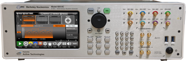
A second pulse after the programmed one
The symptom: one pulse is programmed and the device under test receives two, the intended pulse and a smaller copy of it a few nanoseconds later, with ringing (Figure 1). A series resistor or an in-line capacitor at the output damps the reflection and suppresses the second pulse. It also changes the edge, reduces the amplitude at the load, and places an uncalibrated part between the instrument and the device under test.
Tektronix no longer sells the AWG7000C series, which includes the AWG7082C, so units in service are supported from the used and rental market.
Why the second pulse shows up
A second pulse at a fixed delay after the first is the signature of a reflection. A fast edge launched into a load that is not 50 Ω partly reflects; the reflected edge travels back to the source, and whatever the source does not absorb is sent toward the load again. The second pulse arrives one cable round trip after the first, about 10 ns per meter of cable in solid-dielectric coax (velocity factor 0.66). Any fast source shows this into a mismatched load. The size of the second pulse depends on the load mismatch and on how closely the source matches 50 Ω across the bandwidth of the edge. If a blocking capacitor sits in the path, the drive is also AC-coupled, and the baseline shifts with the duty cycle of the pattern.
A series resistor attenuates both the pulse and its reflection; a series capacitor blocks DC and makes the baseline depend on duty cycle. Terminating the device under test in 50 Ω, or keeping the cable short compared with the pulse width, removes the cause.
The Model 685 output
The Model 685 single-ended output is DC coupled with a 50 Ω output impedance, and it delivers up to 5 Vpp into 50 Ω with a ±2.5 V hardware offset, so the baseline sits at the programmed level without a blocking capacitor. A reflection returning from the load is terminated in the 50 Ω source impedance instead of being sent back as a second pulse; the mismatch at the load itself remains, and a 50 Ω termination at the device under test removes it. In True Arb mode, rise and fall time is ≤ 110 ps (20% to 80%) and ≤ 175 ps (10% to 90%) at 1 Vpp single-ended, and random jitter on a clock pattern is < 2 ps rms. In AFG mode, square and pulse edges are 300 ps (20% to 80%) and 400 ps (10% to 90%).
The 685 also generates a double pulse on purpose. In AFG mode the double pulse is a standard waveform up to 385 MHz, with the two pulse amplitudes summing to 10 Vpp (|Vpp1| + |Vpp2|) single-ended, alongside sine, square, ramp, pulse, Gaussian, noise and arbitrary waveforms. Vertical resolution is 16 bits in every mode: 65,536 levels, 64 times the 1,024 levels of a 10-bit converter, for fine steps and low-level detail in pulse and step shapes.
AWG7082C and Model 685
| Specification | Tektronix AWG7082C | BNC Model 685 |
|---|---|---|
| Product status | No longer sold by Tektronix | Current production |
| Vertical resolution | 10 bit (8 bit with markers) | 16 bit |
| Sample rate | 8 GS/s (16 GS/s interleaved, one channel, Option 06) | 1 S/s to 6.16 GS/s (12.32 GS/s in RF mode) |
| Bandwidth | −3 dB modulation bandwidth, typical: 680 MHz amplified output, 3.2 GHz direct output, 3.5 GHz Option 02 | ≥ 2 GHz calculated (0.35 / rise time), single-ended |
| Rise / fall time, 20% to 80% | Typical: 350 ps amplified, 75 ps direct, 35 ps Option 02 | ≤ 110 ps True Arb at 1 Vpp single-ended; 300 ps AFG |
| Output level | Typical, single-ended: −22 dBm to 10 dBm amplified, −22 dBm to 4 dBm direct | 0 to 5 Vpp into 50 Ω, single-ended, DC coupled |
| Offset | ±0.5 V amplified output; none listed on the direct output | ±2.5 V into 50 Ω |
| Random jitter, clock pattern, rms | Typical: 1.6 ps amplified, 0.9 ps direct | < 2 ps (typical) |
| Channels | 2 (1 interleaved) | 2, 4 or 8 |
| Waveform length | 32 M points (64 M with the record length option) | 128 to 2 G samples per channel (4 G optional) |
Model 685 values are from the Berkeley Nucleonics Model 685 datasheet. AWG7082C values are from the Tektronix AWG7000 Series datasheet, literature number 76W-22259-18, and are typical where that datasheet marks them typical. The AWG7082C leads on sample rate, direct-path bandwidth, edge time and jitter. The Model 685 leads on vertical resolution, output amplitude and offset into 50 Ω, channel count and waveform memory. For applications that need more than 6.16 GS/s, the Model 686 samples at up to 20 GS/s with 14-bit resolution.
More than a clean pulse
- Resolution. 16 bits, 64 times the levels of a 10-bit converter, for pulse shapes, fine steps and low-level detail.
- A DC-coupled output. Up to 5 Vpp into 50 Ω with a ±2.5 V offset, so a device whose input sits within that window is driven without an external resistor, capacitor or amplifier.
- A current product. Calibration, warranty and service from Berkeley Nucleonics.
- Room to grow. Two, four or eight channels, up to 2 G samples per channel (4 G optional), and a sequencer with up to 16,384 entries, loops, jumps and conditional branches.
- The double pulse as a setting. A double-pulse waveform in AFG mode when the test calls for one.
See it on your own pulse
Send us the waveform and the load you drive from an AWG7000. We will reproduce it on a Model 685 into the same load and compare the two edges on one oscilloscope. Let's look at the results together.
Request a Model 685 demo or explore the Model 685 data sheet.