What phase noise is
An ideal oscillator would produce a single, infinitely thin spectral line. Real sources do not. Tiny random fluctuations in the phase of the carrier spread energy into a skirt on either side of the intended frequency. That skirt is phase noise. In the time domain it shows up as jitter. In the frequency domain it shows up as a continuous pedestal of power surrounding the carrier, and it is the measure of spectral purity that sets the floor for most measurements the source takes part in.
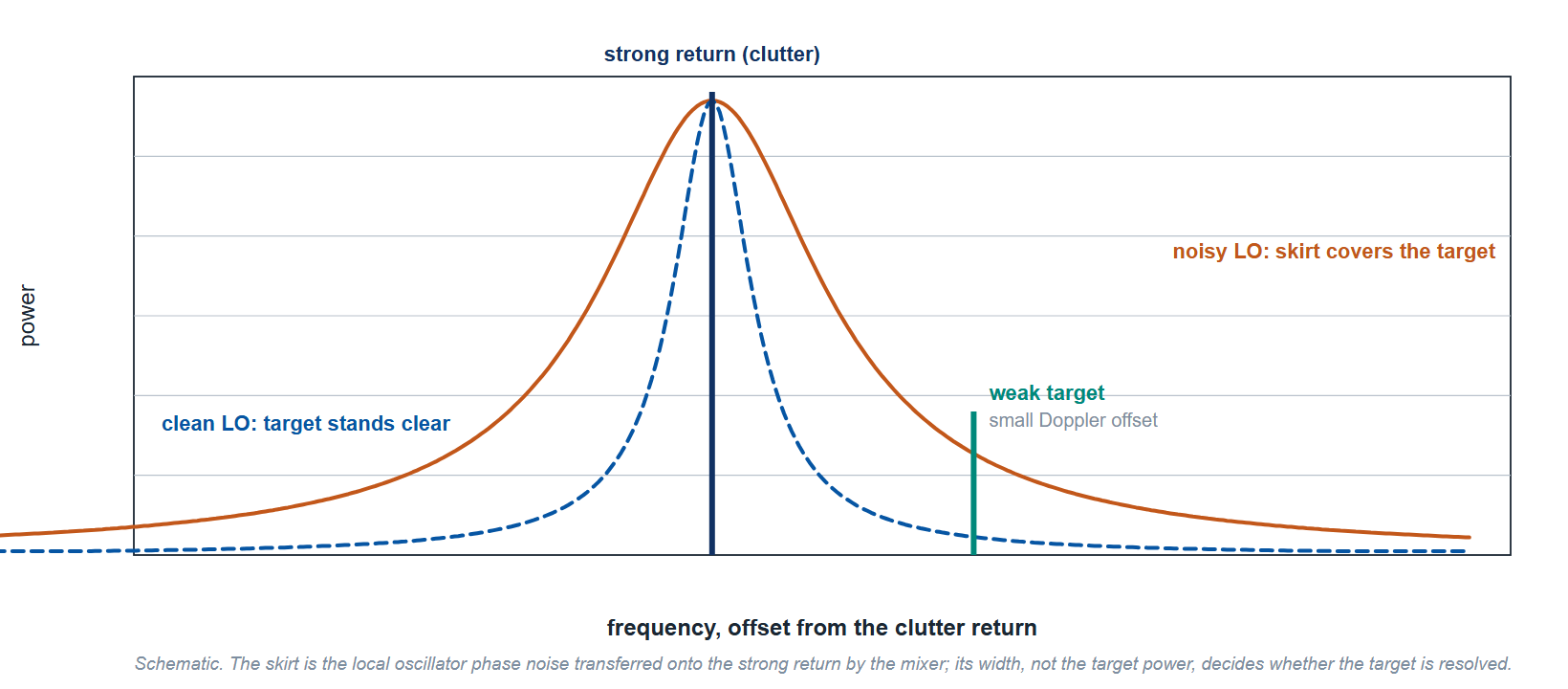
Phase noise matters because it does not stay confined to the source. It transfers, by mixing and by frequency multiplication, into every measurement the source takes part in. A receiver tested with a noisy local oscillator measures worse than it is. In a radar, reference phase noise at the Doppler offset of a slow target sets how far below the clutter return that target can still be detected. Source phase noise adds to the measured phase noise of the device, so the source contribution has to be small at the offsets of interest.
Reading the specification: dBc/Hz at an offset
Single sideband phase noise is quoted in dBc/Hz at a stated offset from the carrier. The unit has three parts. The "dBc" part means decibels relative to the carrier power. The "/Hz" part normalizes the measurement to a one hertz bandwidth, so two instruments measured differently can still be compared. The offset, written as 1 kHz, 20 kHz, 10 MHz and so on, tells you how far from the carrier the measurement was taken.
A figure of -132 dBc/Hz at a 1 kHz offset means that, one kilohertz away from the carrier, the noise power in a one hertz bandwidth is 132 dB below the carrier. More negative is better. Because the offset is always part of the number, a single phase noise figure is incomplete without its offset and carrier frequency. A source can be excellent close to the carrier and ordinary far out, or the reverse, so sources are compared across a curve of offsets rather than at one point.
Close-in versus far-out
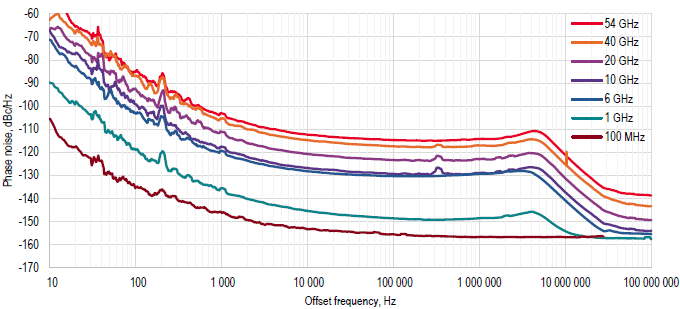
Phase noise behavior changes with offset, and different applications care about different parts of the curve. Close-in noise, roughly 10 Hz to a few kilohertz, is dominated by the reference oscillator and the loop that locks to it. This region governs slow drift, coherence between channels, and the ability to resolve closely spaced tones. Far-out noise, from tens of kilohertz to tens of megahertz, is set by the output stages and the noise floor, and it governs wideband interference and adjacent channel behavior.
A high-quality OCXO reference and a well-designed loop push the close-in numbers down. Clean output amplification and filtering push the far-out floor down. The two are engineered separately, which is why options such as enhanced close-in phase noise (often labeled LN or LN+) target one region without changing the other.
Why it matters: radar, communications, quantum
In radar, reciprocal mixing of local oscillator phase noise onto a strong clutter return can mask a weak moving target nearby in frequency. Close-in phase noise directly limits the smallest Doppler shift a system can resolve, so pulse-Doppler and coherent radars need the lowest close-in phase noise the budget allows.
In communications, phase noise corrupts the constellation. Higher-order schemes such as 256-QAM pack symbols tightly, and a noisy carrier blurs the boundaries between them, raising error vector magnitude and the bit error rate. Testing a modern transceiver fairly requires a source that is quieter than the device under test.
In quantum work, microwave sources act as local oscillators for I/Q mixers and as pump tones for parametric amplifiers. Phase noise on those tones translates into qubit dephasing and gate error, so the source budget feeds directly into coherence time. In all three fields the source phase noise has to be below that of the device or system at the offsets being measured.
How Berkeley Nucleonics sources compare
Table 1 lists single sideband phase noise at a 1 GHz carrier for representative models, cell by cell from the current datasheets, with the offsets the datasheets publish. Use it as a starting point and confirm the full offset curve against the datasheet for any critical design.
| Model | Frequency range | 10 Hz | 1 kHz | 20 kHz | 100 kHz | Value type |
|---|---|---|---|---|---|---|
| 870A | 10 MHz to 54 GHz (9 kHz with Option 9K) | -80 (-100 with LN or LN+) | -132 | -145 | -148 | Specified maximum; typical values run 5 dB lower |
| 871 | 10 MHz to 51 GHz (1 kHz with Option 1K) | -80 (-100 with LN or LN+) | -143 | -150 | -150 | Specified maximum |
| 855B | 300 kHz to 6, 12, 20, 33 or 40 GHz | -87 (-98 with LN) | -130 | Not published | -145 | Typical at maximum output power, ALC off; specified maximum -76, -125 and -140 |
| 865B-M | 100 kHz to 40 GHz (8 kHz with Option 8K) | -93 (with LN or LN+) | -130 | Not published | -145 | Typical |
| 875 | 10 MHz to 40 GHz (100 kHz with Option 100K) | -87 (-98 with LN) | -130 | -145 | -150 | Typical, +10 dBm output |
| 845-M | 10 MHz to 20 GHz | Not published | -118 | Not published | -128 | Typical |
All values are at a 1 GHz carrier. The last column says whether a row is a warranted maximum or a typical value, because the datasheets specify the models differently, and a typical value is not a guarantee. Phase noise rises with carrier frequency: an ideal multiplier adds 20 log N dB for a frequency ratio N, and the 870A datasheet shows 15 dB between 1 GHz and 10 GHz at 1 kHz offset. The LN and LN+ options act on the close-in region, which is why they change the 10 Hz column and not the 100 kHz column. Entries marked "Not published" have no datasheet figure at that offset; an application engineer can supply the measured curve.
Talk to an application engineer
Phase noise requirements are best evaluated against the full offset curve at the carrier frequency of the application, not a single headline figure. Berkeley Nucleonics application engineers can match a source to your radar, communications, or quantum budget and supply the measured curves to back it. For specifications, configurations, and quotations, contact info@berkeleynucleonics.com or call 800-234-7858. The full family overview is on the RF & Microwave Signal Generators documentation page.
Ask now → Chat with our assistant and get an answer in seconds.