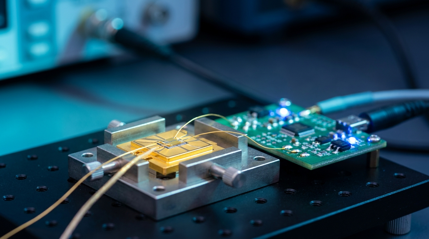
Pulsed Laser Diode Test
A pulsed laser diode bench has three electrical jobs. It times the pulse, it shapes the pulse, and it supplies the current. The first two are signal problems: a gate or a waveform at a known instant, with edges and widths the measurement can rely on. The third is a power problem. A diode above threshold presents a forward drop of about 2 V and a dynamic resistance of a few ohms, and a pulsed emitter for range-finding or lidar takes amperes to tens of amperes through it. The instrument that defines the timing and the instrument that delivers the current are built around different output stages, and the bench works best when each does the job its output stage was built for.
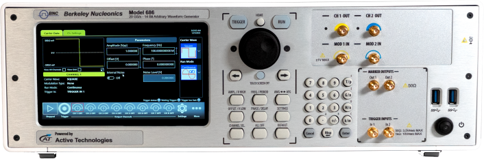
Timing and shaping are the arbitrary waveform generator's job. The Berkeley Nucleonics Model 686 is a 50 ohm voltage source: 5 Vpp into 50 ohm, 14-bit vertical resolution, sample rates to 20 GS/s. In pulse mode it sets the width from 150 ps to the period less 150 ps in 20 ps steps and the edge time from 120 ps upward in 2 ps steps, with jitter below 2 ps rms for edges of 400 ps or longer and overshoot under 2 percent at 1 Vpp. In True Arb mode a stored waveform plays at 50 ps per sample with edges of 70 ps or less (10 to 90 percent, 1 Vpp). Those numbers decide how precisely a gate lands and how clean a shaped drive waveform is.
What a 50 ohm source does not do is supply drive current. At its rated 5 Vpp into 50 ohm the output reaches 2.5 V peak, which is 50 mA into a matched load. Into a laser diode the generator's own 50 ohm source impedance limits the current to the voltage left after the forward drop: with 2.5 V at the output and 2.0 V across the junction, 0.5 V over 50 ohm is 10 mA. That is modulation current for a continuous-wave diode held above threshold by a DC bias. It is not the pulsed drive a range-finder emitter needs, which a current driver supplies in amperes. Figure 1 shows how little of the L-I curve a 50 ohm source reaches on its own.
Pairing the Model 686 with a current driver
The Berkeley Nucleonics DEI drivers are current sources built for the diode side of the bench. Three cover most pulsed-diode work, and Table 1 lists the numbers that decide between them.
| Driver | Output current | Pulse width | Edges and jitter | Gate or trigger input |
|---|---|---|---|---|
| PCO-6131 module | 1 to 125 A | Under 100 ns to DC, single shot to 500 kHz, duty to 100 percent | Rise adjustable from under 30 ns to over 2.5 µs; jitter under 3 ns, first sigma | +5 V CMOS gate, positive edge |
| PCO-6141 module | Up to 60 A | 200 ns to DC (100 ns at 6 V compliance), single shot to 500 kHz, duty to 100 percent | Rise adjustable from under 12 ns to over 1.5 µs; jitter under 3 ns, first sigma | +5 V CMOS gate, positive edge |
| PCX-7401 instrument | 0 to 3 A in 1 mA steps, bias 0 to 0.55 A | 100 ns to DC, external trigger to 2 MHz | Rise and fall 100 ns or less; cycle-to-cycle jitter 25 ns or less on the internal trigger | 0 to 5 V, 50 ohm or 10 kohm; delay about 130 ns to output |
In every case the Model 686 drives the gate or trigger input. Set the AFG pulse to 5 Vpp into 50 ohm with a +2.5 V offset so the gate swings from 0 to 5 V, and the driver's current pulse follows the gate: the PCO-6131 holds the current for the length of the gate, from under 100 ns to DC, at up to 500 kHz. Pulse width, repetition rate, burst count and the order of shots are then set on the generator, with 20 ps width resolution and a sequencer of up to 16,384 entries with loops and conditional jumps, while the amplitude is set on the driver. Figure 2 draws the chain.
The timing budget of the pair is set by the driver rather than by the generator. The Model 686 contributes under 20 ps rms of trigger-to-output jitter in AFG mode and under 2 ps rms on the pulse itself; the PCO-6141 is specified at under 3 ns first sigma, and the PCX-7401 at 25 ns or less cycle to cycle on its internal trigger. The fixed delays are deterministic and are budgeted rather than removed: the PCO-6131 gate-to-current delay, which its datasheet does not publish and is worth measuring once on the bench; about 130 ns through the PCX-7401 external trigger, and under 205 ns from the generator's trigger input to its analog output in AFG mode. The optical pulse is captured against the generator's marker output (jitter under 10 ps rms, skew to the analog channel accurate to 1 percent of the setting plus 50 ps), so those delays enter a time-of-flight measurement as one constant offset.
Where the Model 686 drives the optics directly
Two cases take the generator's output straight to the optical side. A continuous-wave diode biased above threshold through a bias tee accepts the Model 686 as its modulation source: a few tens of milliamps of signal current at the diode, with the generator's 5.8 GHz measured analog bandwidth, not a driver, setting the modulation limit. An electro-optic intensity modulator on a continuous-wave source is the other case. A waveguide modulator whose half-wave voltage lies within a 5 V swing takes its drive from the Model 686 directly, and the shaped optical pulse then carries the generator's 70 ps edges and 14-bit amplitude shaping with nothing else in the path. Where the modulator needs more than 5 V, a modulator driver amplifier follows the generator, which remains the timing and shaping source.
Recommended configuration
For characterizing pulsed emitters at amperes, range-finder and lidar diodes among them, use a two-channel Model 686-2C-SE (5 Vpp single-ended outputs) gating a PCO-6141 or, above 60 A, a PCO-6131 current driver. Channel 1 is the gate; channel 2 or a marker output triggers the digitizer; a fast photodiode reads the optical pulse. Width, rate and sequence are set on the generator, current on the driver. For L-I curves, threshold and slope efficiency on single emitters and small arrays, pair the generator with a PCX-7401, whose 1 mA current steps and separate bias output place the operating point. For direct modulation of a continuous-wave diode or of a waveguide modulator, the generator works alone.
Limitations. The Model 686 does not drive a pulsed laser diode directly: 50 mA into 50 ohm is its output ceiling. It does not sense diode current or voltage; the driver's current monitor does (1000 A/V on the PCO-6131 with its optional PCA-9155 monitor, 125 mV/A on the PCX-7401, both into 50 ohm). Diode protection also lives in the driver: reverse-voltage clamping and undervoltage lockout on the PCO modules, and on the PCX-7401 an output that is shorted to ground whenever it is not enabled, an interlocked output cable and a key switch.
Talk to an application engineer
Berkeley Nucleonics can help you pair a Model 686 with the right DEI current driver for your pulsed laser diode bench. Call 800-234-7858 or email info@berkeleynucleonics.com. Specifications: Model 686 datasheet, PCO-6131 datasheet, PCO-6141 datasheet, PCX-7401 datasheet.
For a quick question, chat with an engineer at berkeleynucleonics.com.
Ask now → Chat with our assistant and get an answer in seconds.