
Radar, satellite and telecommunications systems depend on power measured at known points in the chain: a transmitter output, an IF level, a received carrier. The Model 12100 Series measures true-RMS average power from 9 kHz to 67 GHz on its coaxial models and to 75 GHz with the WR-15 waveguide Model 12175, over a dynamic range of -60 to +26 dBm on the coaxial models (-50 to +18 dBm on the Model 12175). Typical total RSS error runs from 1.09 percent on the Model 12108S to 3.73 percent at 54 GHz on the Model 12154L, and is 5.36 percent on the waveguide Model 12175.
The sensors plug into a host computer over USB and run with no external meter, no zeroing and no pre-use calibration, so a measurement starts within minutes on the bench or in the field. A patented thermal-stability method holds the measured reading at 1 GHz within hundredths of a dB from 0 to 50 °C; the specification is 0.5 percent (0.02 dB) from 10 to 40 °C and 2.5 percent (0.11 dB) from 0 to 10 °C and 40 to 55 °C.
Satellite Communications
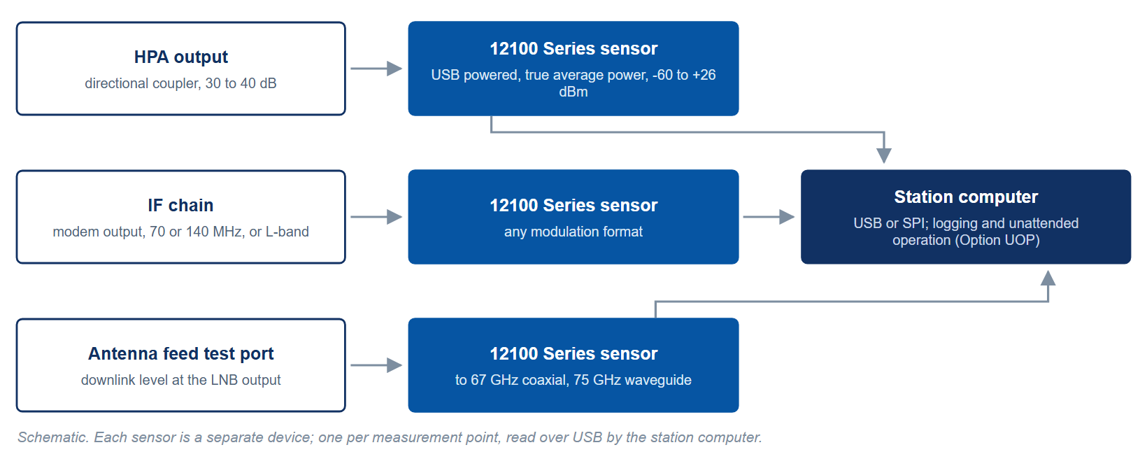
At a ground station the sensor reads the uplink level at a coupler on the high-power amplifier output, the IF level at the modem, and the downlink level at the LNB output, so each stage of the chain can be set to its design level and logged against time. The reading does not depend on the modulation on the carrier. With Option UOP the sensor logs unattended, time-stamped by its internal clock, into non-volatile memory that holds 50 million measurements at up to 1,000 measurements per second, with power supplied over a USB power-only cable or the optional SPI ribbon cable.
Measuring Any Modulation
The sensors measure average power on any modulation, including 802.11ac, GSM, CDMA2000, CDMA (IS-95), TDMA, multi-tone, OFDM, QAM and CW. Average mode reads from -60 dBm with a noise specification of 0.5 nW below -40 dBm; normal mode adds gated and triggered measurement with gates down to 1 µs, and the trigger input accepts an external pulse with a 25 ns minimum width, which is what a pulsed radar measurement needs.
Because the sensor is a USB device with a SCPI command set, the same unit serves automated test, direct control through the optional SPI or I2C port, manufacturing and R&D. In a radar transmitter the sensor on a coupler chosen to keep the coupled peak within +23 dBm and the energy per pulse within 20 W·µs reads the true average of the pulse train directly, without a duty-cycle correction; in a satellite chain it logs the uplink and downlink levels; in a telecommunications rack it monitors a test point for weeks without an operator.
For more information, visit the Model 12100 Series product page, or contact info@berkeleynucleonics.com or call 800-234-7858.