
LiDAR & Laser Rangefinding
A pulsed time-of-flight system measures distance by timing the interval between an emitted laser pulse and its return: the range is R = c × t / 2, where t is the round-trip time and c is 2.998 × 10⁸ m/s. The optical pulse follows the current pulse that drives the diode, so the driver's pulse width, rise time and timing jitter bound how finely the system can range. The same three quantities carry the signal in atmospheric optical communication, where pulse shape and timing encode the data.
Berkeley Nucleonics, through its Directed Energy Division, builds high-current drivers for this work. The PCO-6141 and PCO-6131 modules produce fast current pulses into pulsed laser diodes and are built for OEM integration, so a sensor builder can embed the driver inside a finished instrument. The PCX-7421 bench source covers emitter characterization during development.
The challenge
Range resolution in a pulsed system is tied directly to the emitted pulse. A shorter, sharper optical pulse lets the receiver separate returns that arrive close together, while a slow or wide pulse blurs the timing and coarsens the measurement. That puts the burden on the driver to deliver a fast rise and a tightly controlled width into a diode that may draw tens of amps, or more than a hundred, during the pulse. High current and a fast edge pull against each other because the inductance of the loop between driver and diode limits the current slew rate to the available voltage divided by that inductance. With 20 V of headroom across 10 nH, the current can rise no faster than 2 A/ns, so a 60 A step takes at least 30 ns.
There is a second tension. Different ranging tasks want different pulses. A short-range, high-resolution scan favors the fastest, narrowest pulse the diode can survive, while a long-range shot may favor more energy in a wider pulse. A driver fixed to one rise time forces a compromise on the sensor designer, so the ability to set the edge is a system-level capability rather than a detail. And because an OEM driver lives inside the product, it has to fit the enclosure, run from the available supply rail (+24 VDC for the PCO-6131 and PCO-6141), and accept a gate from the host without adding delay or jitter the timing budget cannot absorb.
The link between pulse width and range is direct. Two returns separate only when the gap between them exceeds the emitted pulse width τ, so the two-target range resolution is ΔR = c × τ / 2: 1.5 m for a 10 ns pulse, 7.5 m for 50 ns and 15.0 m for 100 ns. The shortest pulses from the drivers below are under 100 ns on the PCO-6131, 100 ns on the PCO-6141 (at 6 V compliance) and 50 ns on the PCX-7421 under external trigger. Single-target precision is set at the leading edge instead. Each nanosecond of uncertainty in the moment the timer keys on is c × 1 ns / 2 = 15 cm of range, and a slow edge widens that uncertainty for a given noise level (Figure 1). Where the timer starts from the gate signal rather than from a pickoff of the emitted light, the driver's own jitter adds directly: under 3 ns (first sigma) on the PCO-6131 and PCO-6141, or 45 cm. A driver that controls both the width and the edge therefore controls the two quantities that bound a pulsed system's resolution and precision.
The BNC approach
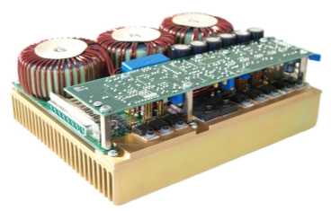
The DEI OEM modules are fast current sources with the edge under the integrator's control. Rise time is set with a PCB-mounted trimpot: from under 12 ns to over 1.5 µs on the PCO-6141 and from under 30 ns to over 2.5 µs on the PCO-6131 (10 to 90 percent). One module design can therefore serve a fast-edge, short-range sensor and a softer-edge, long-range sensor, with the edge matched to each diode during integration and traded against overshoot and pulse energy where the application calls for it.
The modules are built to drop into a sensor (Figure 2). Each takes a +5 V CMOS gate that sets pulse width and timing, a TTL enable, and a single +24 VDC supply, and delivers its output through a PCB-mounted high-current DSUB. The output stage and the cabling are treated together, because a fast edge into a low-impedance diode survives only if the path between driver and emitter stays low in inductance. Keep that connection short and tightly paired and the diode sees the edge the driver produced; lengthen it and the edge slows, by the di/dt limit above, and ranging precision falls with it.
For the fastest adjustable edge, the PCO-6141 delivers up to 60 A with rise time from under 12 ns, pulse widths of 100 ns (at 6 V compliance) and from 200 ns to DC, and repetition from single shot to 500 kHz at up to 100 percent duty. Where the emitter needs more current, the PCO-6131 delivers up to 125 A with rise time from under 30 ns, pulse widths from under 100 ns to DC and the same 500 kHz ceiling; its datasheet captures show under 30 ns rise with under 750 ns fall at 120 A. Both modules accept diode forward voltages up to 20 V and specify jitter under 3 ns (first sigma). For emitter characterization on the bench, the PCX-7421 supplies up to 21.5 A with rise time under 25 ns and a 50 ns minimum pulse width under external trigger, at up to 1 MHz.
Recommended instruments
Choose by the peak current the emitter needs, the shortest pulse the range resolution requires (τ = 2ΔR / c, so 15 m calls for 100 ns or less), and the edge speed the timing budget needs.
- PCO-6141: OEM module, up to 60 A, rise time adjustable from under 12 ns to over 1.5 µs, pulse width 100 ns (at 6 V compliance) and 200 ns to DC, single shot to 500 kHz. The fastest adjustable edge of the drivers on this page.
- PCO-6131: OEM module, up to 125 A, rise time adjustable from under 30 ns to over 2.5 µs, pulse width under 100 ns to DC, single shot to 500 kHz, for higher-current emitters and longer-range work.
- PCX-7421: bench current source, 50 mA to 21.5 A pulsed, rise time under 25 ns, 50 ns minimum pulse width under external trigger to 1 MHz, 24 V compliance, for characterizing an emitter before it is integrated.
Getting started
Begin with the ranging requirement and work back to the pulse. Decide the minimum range resolution you need and the maximum range you have to reach, then translate that into a target pulse width and rise time at the emitter. Pick the diode and its peak current, choose the module whose current and rise-time range cover the task, and plan the trigger interface and the low-inductance connection to the diode early, because both shape the timing the finished sensor delivers. Talk to a BNC applications engineer at info@berkeleynucleonics.com or 800-234-7858 to match a driver to your sensor and integration.