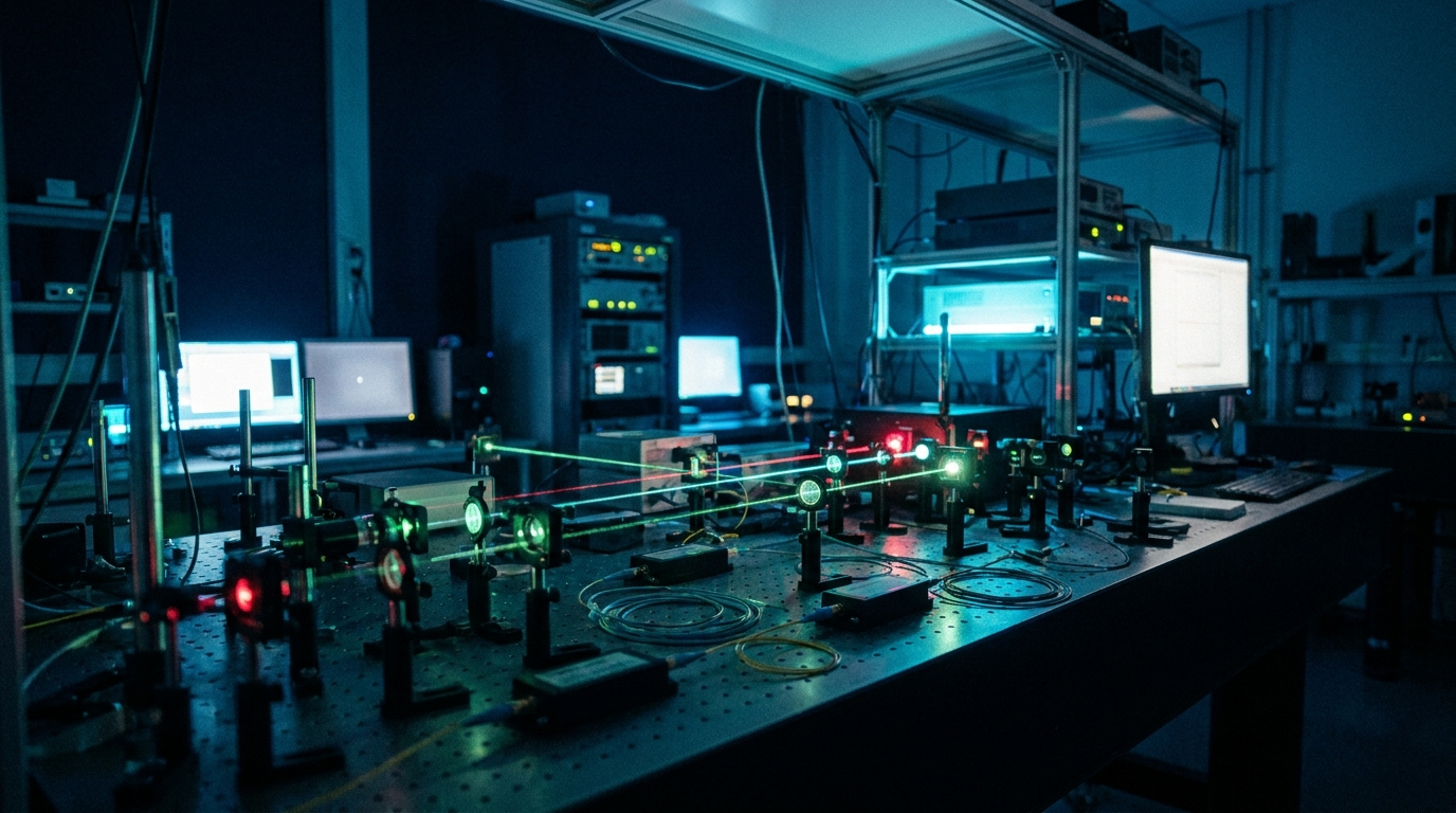
Optics & Photonics
Electro-optic and acousto-optic modulators, Pockels cells and directly modulated laser sources convert an electrical drive waveform into a change in a light field. The shape of the optical pulse, the steepness of its edges and the timing relationship between channels are set by the electrical drive, so the generator's edge speed, amplitude resolution and timing appear in the optical result.
The work spans several recurring tasks. Pulse carving slices a continuous-wave beam into a defined train, which demands sharp, well-controlled edges. Intensity shaping writes an arbitrary envelope onto the light for spectroscopy, ranging, or quantum-state preparation, which demands fine amplitude resolution. Pre-distortion, sometimes called pre-compensation, shapes the drive waveform with the inverse of the modulator's measured transfer curve so that the optical output follows the intended envelope. Multi-channel experiments add the requirement that several drives, pump and probe, gate and signal, modulator and trigger, stay locked together to a known phase.
The challenge
These tasks place a specific and demanding set of requirements on the generator. Sharp optical pulses need fast rise and fall times and the analog bandwidth to support them, because a slow electrical edge becomes a slow optical edge no matter how good the modulator is. Intensity shaping needs fine vertical resolution, since the small voltage steps that define a smooth envelope are lost on a coarse converter. Long experiments, a full ranging sequence or an extended quantum protocol, need deep waveform memory so the pattern does not have to loop before the science is done. Underlying all of it, the drive has to be quiet: low timing jitter so the optical pulse lands where it should, and the ability to deliver real amplitude directly into a 50 ohm modulator input without an external amplifier in the path adding noise and delay.
Converter speed and vertical resolution trade against each other: the Model 686 samples at 20 GS/s with 14 bits, and the Model 685 at 6.16 GS/s with 16 bits. Photonics work that carves edges and shapes envelopes on the same channel needs both properties from one source, and the choice between the two instruments follows from which one limits the experiment.
Direct drive also removes a stage. An external amplifier between the generator and a 50 Ω modulator adds its own bandwidth limit, noise floor and propagation delay, and a generator that swings the modulator directly removes that stage and the uncertainty that comes with it.
How the Model 686 solves it
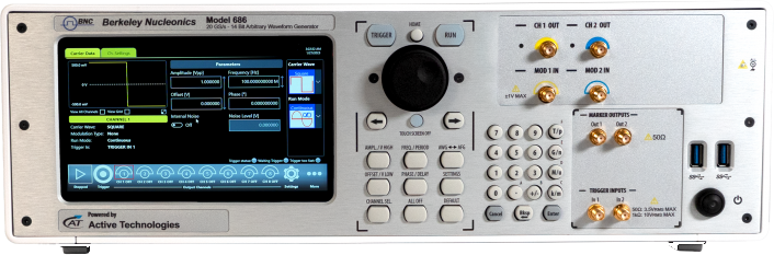
The Model 686 (Figure 2) samples at up to 20 GS/s. In True Arb mode its measured 3 dB bandwidth is 5.8 GHz (sin(x)/x compensated), and its rise and fall times are 50 ps or less from 20% to 80% and 70 ps or less from 10% to 90%, both at 1 Vpp single-ended (45 ps and 60 ps on the differential models). In AFG mode it generates sine waves to 6.5 GHz and pulses as narrow as 150 ps. The single-ended models drive up to 5 Vpp into 50 Ω. Where an electro-optic or acousto-optic modulator's required swing is within that, the generator drives it directly, and the modulator sees one source rather than a generator followed by an amplifier chain.
For shaping work the Model 686 carries 14-bit vertical resolution. Modulator linearization is done in the waveform itself: measure the modulator's transfer curve, compute the pre-distorted drive in analysis software, and load the result as the arbitrary waveform. In True Arb mode at full rate, CH1 (and CH3 on the 4-channel models) holds up to 9.6 Gsamples, 0.48 s of waveform at 20 GS/s, for long non-repeating sequences; CH2 holds 1.17 Msamples on the 2-channel models, and CH2 and CH4 hold 589 ksamples on the 4-channel models. Channel-to-channel skew is adjustable with 100 fs resolution (between CH1 and CH2 on the 2-channel models; between the CH1/CH2 and CH3/CH4 pairs on the 4-channel models), which sets the relative timing of pump and probe, or of modulator and trigger.
Edge timing is specified two ways. Random jitter on a clock pattern is under 2 ps rms, and Trigger In to output jitter is 0.29 × DAC clock period rms in True Arb mode (14.5 ps rms at 20 GS/s) and under 20 ps rms in AFG mode. When the carved pulse train starts on an external trigger, budget the trigger figure; the clock-pattern figure describes the output edges themselves.
Where amplitude resolution comes before edge speed, the Model 685 offers 16-bit vertical resolution at up to 6.16 GS/s, with True Arb rise and fall times of 110 ps or less (20% to 80%) and 175 ps or less (10% to 90%) at 1 Vpp single-ended, and up to 5 Vpp into 50 Ω. Its two extra bits give four times as many amplitude levels as the Model 686, which suits high-dynamic-range intensity shaping and fine modulator linearization.
Recommended configuration
For a bench that carves pulses, gates beams and drives modulators with fast edges, start with the Model 686 at 20 GS/s: 5.8 GHz measured bandwidth, edges of 50 ps or less (20% to 80%, 1 Vpp single-ended), and up to 5 Vpp into 50 Ω for direct drive of modulators whose required swing is within it. Load pre-distorted waveforms computed from the modulator's measured transfer curve, use the channel skew adjustment to set pump-probe or gate-and-signal timing, and put long sequences on CH1 or CH3, which hold 9.6 Gsamples.
Where the experiment depends on high-resolution intensity shaping or fine linearization more than on edge speed, choose the Model 685 for its 16-bit resolution. A bench that needs both can run the Model 686 for carving and gating and the Model 685 for envelope shaping, locked to one external reference clock (5 MHz to 200 MHz on the 685, 5 MHz to 500 MHz on the 686).
Talk to an application engineer
Berkeley Nucleonics can help you match a Model 686 or Model 685 configuration to your optics and photonics bench. Call 800-234-7858 or email info@berkeleynucleonics.com.
For a quick question, chat with an engineer at berkeleynucleonics.com.
Ask now → Chat with our assistant and get an answer in seconds.