Two words people use interchangeably
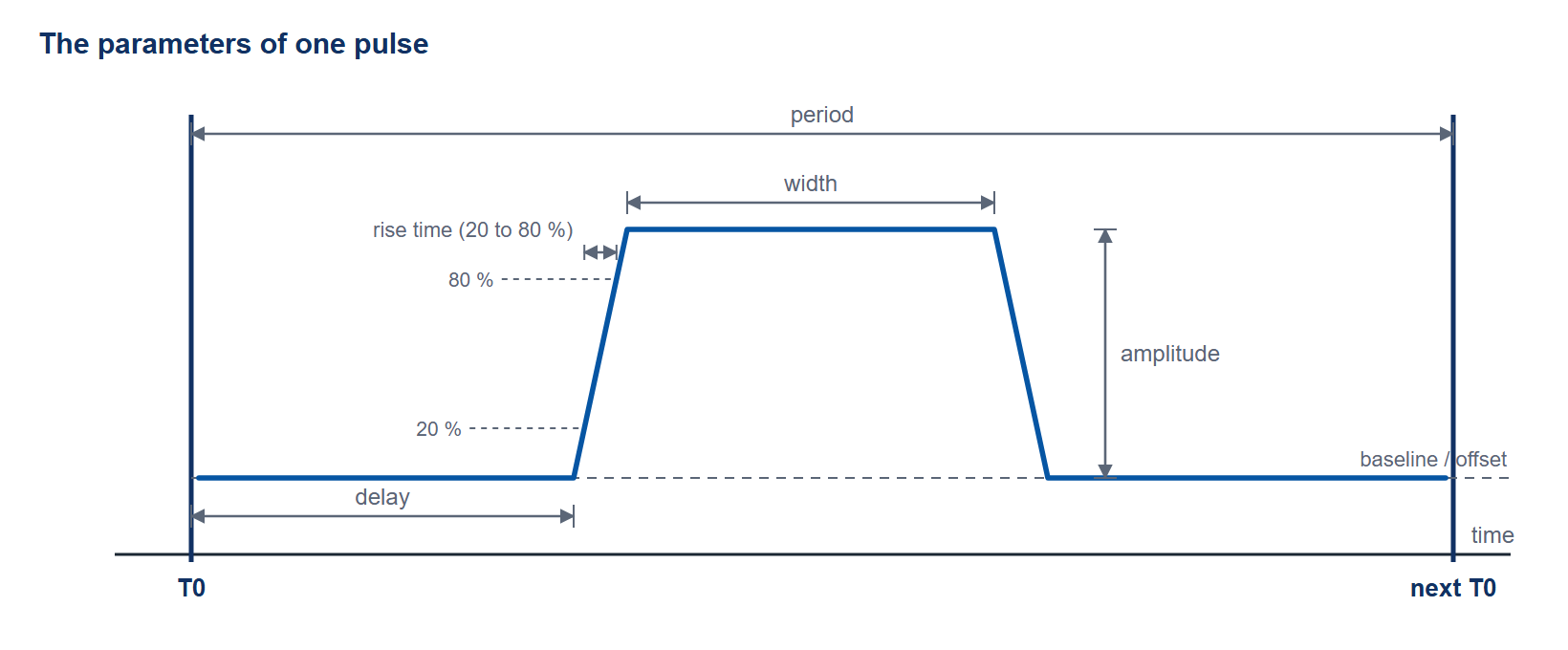
The two names are used for the same instruments, and the hardware draws a sharper line. A delay generator answers the question when. It takes a reference event, called T0, and produces a clean edge a precise interval later. A pulse generator answers what. It produces an output with a defined amplitude, width, polarity, and edge speed, the signal that drives the load. Figure 1 names the parameters each one controls.
Most Berkeley Nucleonics instruments do both. A single channel on a Model 577 sets a delay from trigger, then emits a pulse of programmed width. The distinction still matters, because it tells you which specifications to weigh first. If you are timing a flashlamp before a Q-switch, resolution and channel-to-channel skew dominate. If you are driving a Pockels cell or a 50 ohm detector, amplitude and rise time take over.
When you need delay output
Reach for delay-first behavior when many things must happen in a fixed sequence relative to one start. Laser triggering is the classic case: flashlamps fire, the pump settles, then the Q-switch opens, then a camera gates. Each step is a channel referenced to T0 with its own delay. Particle Image Velocimetry and LIBS work the same way, with two laser pulses and a camera straddling them by microseconds or less.
Here the output is usually a logic-level edge. TTL or CMOS into high impedance is enough to trigger the next box. What you care about is that the edge lands where you asked, shot after shot, with low jitter and minimal drift between channels. The 575, 577, and 588B are built around this model, with 250 ps resolution and independent delay and width per channel.
When you need pulse output
Reach for pulse-first behavior when the output drives something directly. A laser diode, an electro-optic modulator, a sample under test, a 50 ohm transmission line. Now the edge speed and amplitude are the product, not an afterthought. A logic pulse that is electrically correct in timing can still be useless if its rise time is too slow or its level too low for the load.
This is where the 765 family lives. The Model 765 delivers sub-70 ps rise and fall times with adjustable amplitude from 10 mVpp to 5 Vpp into 50 ohms, plus baseline offset. The Model 765-HV reaches 50 Vpp into 50 ohms, placed anywhere in a -25 to +25 V window, while holding rise time under 400 ps (20 to 80 percent). The current pulsers, Model 507 and Model 508, are pulse generators in a different domain entirely: they source current, not voltage, into low-impedance initiators.
Output types you will meet
The output connector hides most of the engineering. A few categories recur across the line.
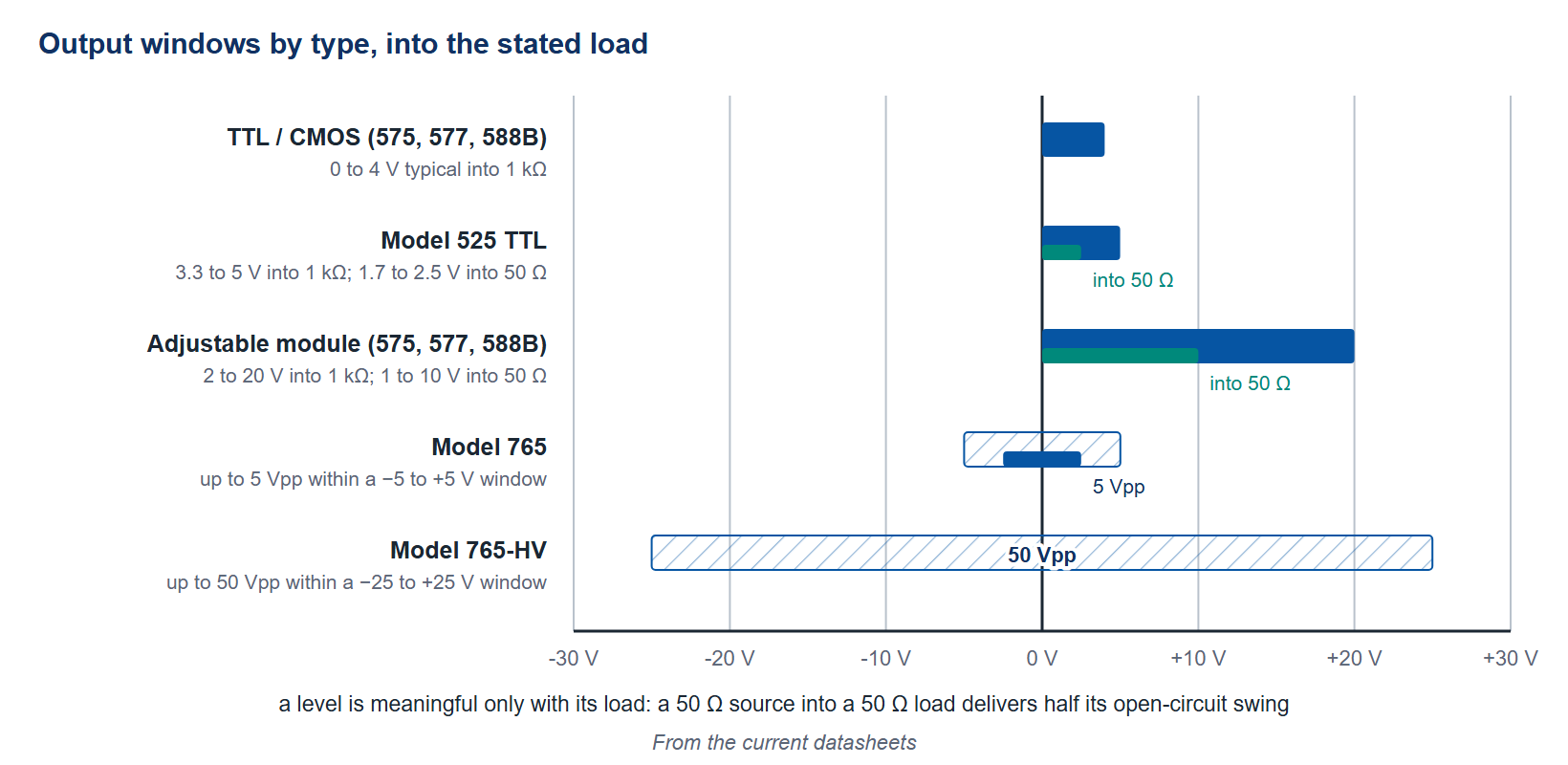
TTL / CMOS logic. A 4 V typical edge into 1 kΩ, the default trigger language between instruments. Standard on the 575, 577, and 588B; the 525 delivers 3.3 to 5 V into 1 kΩ.
Adjustable amplitude. A programmable level, 2 to 20 V into 1 kΩ or 1 to 10 V into 50 ohms, for loads that need more than logic swing. Part of the standard output module on the 575, 577, and 588B.
50 ohm matched. Required for fast edges and long cables without reflections. The 765 is natively 50 ohm; the 575 and 577 offer a 4 V TTL level into 50 ohms through the TZ50 module.
High voltage. Tens of volts of swing for Pockels cells, gating, and beam control. The 765-HV reaches 50 Vpp into 50 ohms within a -25 to +25 V window; the 575 and 577 offer 35 V and 45 V adjustable output modules.
Current. Amperes into a fixed low resistance, for firesets and initiators. The 507 sources up to 25 A; the 508 up to 6 A with current and voltage monitors. Figure 2 draws the voltage windows side by side.
Channel counts and where they cluster
Channel count usually follows the application, not the price. Multi-step laser and imaging sequences want 4 to 8 channels. Dense synchronization across a large experiment wants more. The 588B carries 12 or 24 independent channels, up to 24 outputs, in a 2U chassis. At the other end, the 765-HV ships with one or two channels, each a high-voltage front end.
Model map at a glance
| Model | Primary role | Channels | Output type | Headline spec |
|---|---|---|---|---|
| 525 | Delay + pulse, portable | 6 | TTL, 3.3 to 5 V into 1 kΩ | 4 ns resolution, USB-powered |
| 575 | Delay + pulse, flexible I/O | 2 / 4 / 8 | TTL, adjustable, optical, HV options | 250 ps resolution, up to 10 MHz |
| 577 | Delay + pulse, benchtop | 4 / 8 | TTL, adjustable, optical, HV options | 250 ps resolution, up to 20 MHz |
| 588B | Delay + pulse, high density, 2U rackmount | 12 / 24 | TTL / 20 V adjustable | 250 ps resolution, 50 ps jitter |
| 725 | Multi-trigger logic | 8 in / 8 out | TTL-compatible | 10 ns resolution, programmable logic |
| 745T | Picosecond delay | 4 / 8 | 2 to 5 V into 50 Ω | 1 ps resolution, ~5 ps jitter below 100 ns delay |
| 765 | Fast pulse | 2 / 4 | 50 Ω, 10 mVpp–5 Vpp | <70 ps rise time, 200 MHz (800 MHz in quadruple-pulse mode) |
| 765-HV | Fast high-voltage pulse | 1 / 2 | 50 Ω, up to 50 Vpp in a ±25 V window | <400 ps rise time, 200 MHz (400 MHz in multi-pulse modes) |
| 507 | High-current pulse | 2 / 4 | Current, up to 25 A | 200 ns resolution, fireset |
| 508 | Precision current pulse | 2 / 4 | Current, 0.1 to 6 A | 10 ns RMS jitter, current and voltage monitors |
Table 1. Values from the current datasheets.
How to choose in one pass
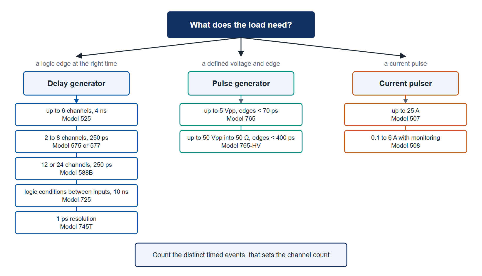
Start with the load. If something downstream needs a specific voltage, current, or edge speed, you are choosing a pulse generator and the output stage decides the model. If the downstream boxes only need a clean trigger, you are choosing a delay generator and resolution, channel count, and jitter decide it. Then check the count of distinct timed events. That sets how many channels you need, and often which chassis. Figure 3 lays the choice out as a flow.
Talk to an application engineer
Send us the loads, the sequence, and the timing budget. We will map it to the right channel count and output type and check it against the released datasheet. Reach Berkeley Nucleonics at info@berkeleynucleonics.com or 800-234-7858, or browse the full Pulse & Delay Generators documentation.
Ask now → Chat with our assistant and get an answer in seconds.