1Why a Current Source, Not a Voltage Source
A laser diode is a diode first. Its current rises steeply once the forward voltage crosses the knee, and above that knee a tiny change in voltage produces a large change in current. Drive a diode from a voltage source set just past the knee and you are balancing on the steep part of an exponential curve. A few tens of millivolts of error, from a warm connector, a noisy supply, or the diode itself heating up, turns into amps of extra current.
That feedback runs the wrong way. More current heats the junction, a hotter junction conducts harder at the same voltage, and harder conduction draws still more current. The loop can run away in microseconds and take the diode with it. A current source breaks the loop (Figure 1). It sets the current you ask for and lets the forward voltage land wherever the diode needs it, so a drifting junction voltage no longer moves the operating point. Every BNC DEI driver in this note is a regulated current source for exactly this reason. If you want the deeper treatment of how a fast driver behaves into a reactive load, see the companion note on driving capacitive loads.
Set the current, not the voltage. A voltage-driven diode sits on the steep side of its I-V curve where small voltage errors become large current errors, and thermal runaway is a real failure mode.
2Compliance Voltage
A current source can only push its rated current if it has enough voltage headroom to do so. That headroom is the compliance voltage: the maximum voltage the driver can develop across everything in the output loop while still regulating current. The loop includes the diode forward drop, the drop across any series resistance, and the drop across the cabling.
Add it up before you assume a driver fits. A diode bar might drop several volts, the harness and connectors add more, and a sense or ballast resistor adds its own share at full current. If the sum approaches the driver compliance, the regulator runs out of headroom at the current peak and the pulse clips. The fix is either a higher-compliance driver or a lower-resistance output path. The mapping table in section 9 lists compliance for each model so you can check headroom against your real load.
Required compliance is the diode forward drop plus the drop across series resistance and cabling at peak current. Leave margin; a driver that barely meets compliance will clip the top of a fast pulse.
3CW, QCW, and Pulsed Operation
Three operating modes cover most laser-diode work, and they trade optical output against heat in different ways. Figure 2 sketches the current waveform of each.
CW, continuous wave, holds a steady current indefinitely. The diode runs at a constant operating point and the full average power has to be removed by the heatsink. CW is the simplest mode and the most demanding thermally.
QCW, quasi-continuous wave, drives the diode hard but only for a burst, typically a few hundred microseconds to a few milliseconds at a low duty cycle. During the burst the diode behaves as if it were CW, but the low duty keeps the average power, and therefore the heat, far below the CW case. QCW lets you reach peak powers a CW setup could not survive.
Pulsed operation drives short, repetitive pulses, from nanoseconds to microseconds, often at high repetition rate. Duty cycle is low, peak current can be very high, and the average power stays modest. Pulsed mode is where edge speed and lead inductance start to dominate the design. For choosing the generator that shapes those pulses, see the companion note on choosing a pulse generator.
4Bias Plus Pulse
Turning a diode on from zero takes time. The junction has to charge and the optical output has to build, and at low current the diode is slow to respond. When you need a fast, clean leading edge, you do not start from zero. You hold a small DC bias just below or near the lasing threshold, then add the pulse on top of that bias.
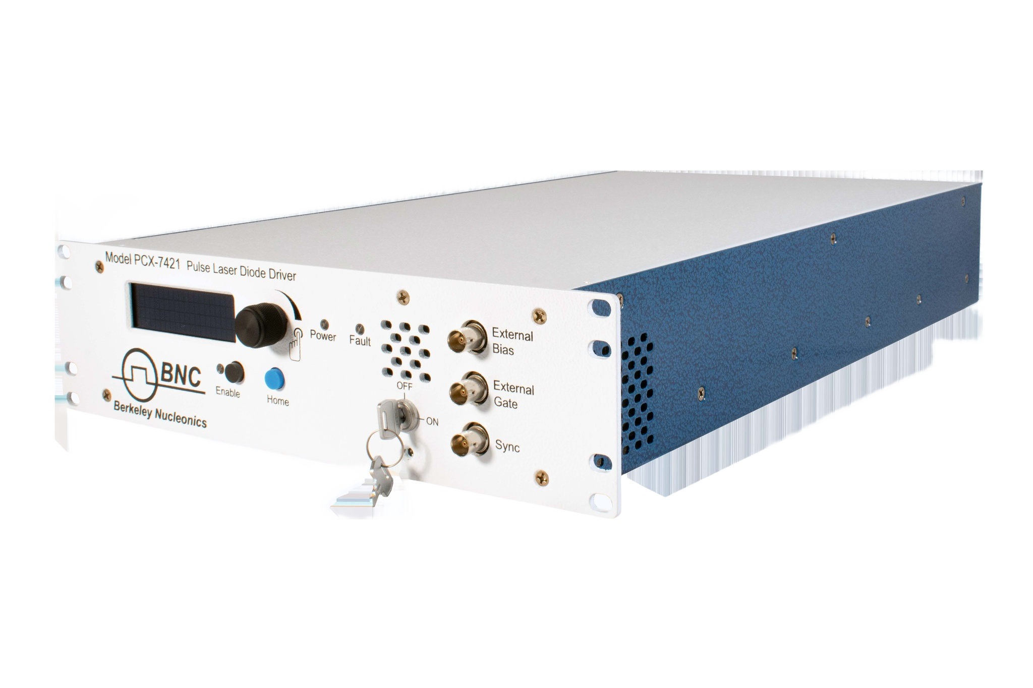
Starting from threshold rather than from zero shortens the turn-on delay and sharpens the edge, because the diode is already primed and only has to swing the pulse amplitude rather than the full operating current. Drivers built for this give you a bias channel and a pulse channel that sum at the output. The trade is a small standing optical output between pulses from the bias current, which is usually acceptable in exchange for the faster, more repeatable edge. The PCX-7401 provides a 0 to 0.550 A bias output beside its 3 A pulse output, and the PCX-7421 holds a CW bias from 0.050 A to 5.8 A and pulses up to 15.7 A above it.
5Rise-Time Control Versus Diode Protection
Faster is not always better. A very fast current edge into a real load rings, and the first overshoot peak can push the diode past its safe current for a few nanoseconds even though the flat top is in spec. That brief excursion is enough to degrade or kill a sensitive diode over many shots.
This is why several DEI drivers offer variable rise-time control. Slowing the edge deliberately, even slightly, lowers the overshoot and keeps the peak within the diode rating. You give up a little edge speed and buy back margin against an overshoot-driven failure. The right setting is the slowest edge the application can tolerate, not the fastest the driver can produce.
Edge speed and overshoot pull against each other. The PCO-6141 (under 12 ns to over 1.5 µs) and PCO-6131 (under 30 ns to over 2.5 µs) set the rise time with a PCB trimpot, so the edge can be slowed during integration until the overshoot sits inside the diode rating.
6Output-Short-on-Disable and Interlocks
A laser diode should never be left floating with charge on it. A floating output can drift up on stray coupling or a discharging filter capacitor, and a slow leakage path through the diode can still deliver damaging current with no regulator in the loop to stop it. The protection is to short the output when the driver is disabled. A clamp across the output places a low-impedance path across the diode the instant the driver turns off, so the diode sees a near-short rather than an open, and any residual charge bleeds through the clamp instead of the junction.
Tie that behavior into an interlock chain. A series loop through enclosure doors, key switches, and emission indicators must be closed before the driver will enable, and breaking the loop at any point disables the driver and engages the output short. The clamp and the interlock work together: the interlock decides when output is allowed, and the short-on-disable makes the disabled state safe for the diode. Wire the interlock so the safe state is the default and emission is the exception. On the PCX-7401 and PCX-7421 the output is shorted to ground at turn-on and whenever it is not enabled; the PCX-7401 adds an output-enable key switch and a cable interlock, the PCX-7421 a front-panel key and a remote interlock, and the PCX-7500-EX disables itself when its output connector is removed.
7Low-Inductance Output Cabling
For fast pulses, the cabling between the driver and the diode is part of the circuit, not a neutral wire. Series inductance in the leads opposes any change in current. The voltage it develops is the inductance times the rate of change of current, so a fast edge into even a small lead inductance demands a large voltage and limits how quickly the current can rise. The same inductance stores energy and rings against the load capacitance, which is where overshoot comes from.
Keep the loop small. Short leads have less inductance than long ones, and a tight, low-area loop has less inductance than a wide one. Use a twisted pair or coaxial cable so the go and return currents run close together and their fields cancel. The numbers are direct: with 20 V of headroom, 10 nH of loop inductance limits di/dt to 2 A/ns, so a 60 A step needs at least 30 ns, while 4 nH allows 5 A/ns and a 12 ns step. The PCX-7401 and PCX-7500-EX are specified with a stripline interconnect of less than 4 nH total for this reason. Treat the diode mount and the driver output as a single low-inductance assembly.
Lead inductance caps di/dt and feeds overshoot. Keep output leads short, keep the loop area small, and use twisted pair or coax so the forward and return currents cancel.
8Thermal and Duty Limits
Peak current sells the driver, but average power sizes the cooling. The heat the diode and driver have to shed is set by the product of current, forward voltage, and duty cycle, not by the peak alone. A pulsed setup at high peak current and low duty can run cool, while a CW setup at modest current runs hot because the duty is one hundred percent.
Two limits follow. The diode needs a heatsink rated for its average dissipation, with enough thermal margin that the junction stays in its safe range across the full ambient swing of the room. The driver has its own average-power and duty limits, and exceeding them, by raising the repetition rate or stretching the pulse width past the rated duty, overheats the output stage even when each individual pulse is in spec. Read the duty and average-power ratings together with the peak rating, and size the cooling for the worst-case average you will run. On the PIM-Mini-200, for example, the maximum duty cycle falls from about 2.8 percent at low current to about 0.4 percent at 200 A, which is a 200 µs pulse at 20 Hz.
9Mapping DEI Drivers to Your Diode
The table maps the BNC DEI laser diode drivers to peak current, repetition rate, rise time and compliance. Read across to the model whose peak current, rate and compliance all clear the load; the datasheet linked in each row carries the full conditions. For rangefinder and LiDAR emitters, the PCO-6141 has the fastest adjustable edge in the table.
| Model | Peak current | Rep rate / pulse width | Rise time | Compliance |
|---|---|---|---|---|
| PCX-7401 | 3 A, plus 0.550 A bias | 5 Hz to 1 MHz; 100 ns to DC | ≤ 100 ns | 15 V |
| PCX-7421 | 21.5 A pulsed/QCW; 5.8 A CW | 40 Hz to 100 kHz (external to 1 MHz); 50 ns to 500 ms | < 25 ns | 24 V |
| PCO-6141 | 60 A OEM module | single shot to 500 kHz; 100 ns (6 V compliance), 200 ns to DC | adjustable, < 12 ns to > 1.5 µs | diode forward voltage to 20 V |
| PCO-6131 | 125 A OEM module | single shot to 500 kHz; < 100 ns to DC | adjustable, < 30 ns to > 2.5 µs | diode forward voltage to 20 V |
| PIM-Mini-200 | 25 to 200 A | single shot to 200 Hz; 25 to 250 µs | ≤ 10 µs above 140 A | diode forward voltage 0 to 48 V; DC input set 12 V above it (12 to 60 V) |
| PCX-7500-EX | 10 to 450 A | 8 Hz to 10 kHz; 4 to 5,000 µs | ≤ 7 µs | up to 110 V from an external DC supply; 1000 W maximum output power |
10Talk to an Engineer
Choosing a driver comes down to matching peak current, compliance, rise time, and duty to a real diode and a real thermal budget, then protecting that diode with short-on-disable and a sound interlock chain. Our applications engineers can walk through those numbers for your diode and thermal budget.
For help choosing, contact a BNC applications engineer at info@berkeleynucleonics.com or 800-234-7858.