Aerospace, Defense & Radar Testing
Aerospace and defense RF work has one problem that defines all the others: the signal that matters is usually the one that is hardest to see. A small return sits next to a much larger one. A frequency-hopping radio dwells on a channel for a few milliseconds and then moves on. A radar pulse lasts a fraction of a microsecond and goes quiet. In a dynamic threat environment, several of these happen at once, and the instrument either captures them on the first pass or loses them entirely.
A swept spectrum analyzer tunes across a band one slice at a time, so anything that appears at a frequency between the sweep’s visits to it is not seen. For steady carriers this is fine. For pulsed radar, agile emitters, and intermittent faults, the gaps are exactly where the answer lives. The classic failure mode is a strong signal masking a weak one. The weak signal is often the threat, the spur, or the unintended emission that the test was designed to find.
The other half of the job is reading the signal once it is caught. Detecting energy tells you something is there. Measuring pulse repetition interval, pulse width, and duty cycle tells you what it is. That distinction, between a blip and a signature, is the entire point of radar and threat test work.
How the ICX-FieldHawk line solves it
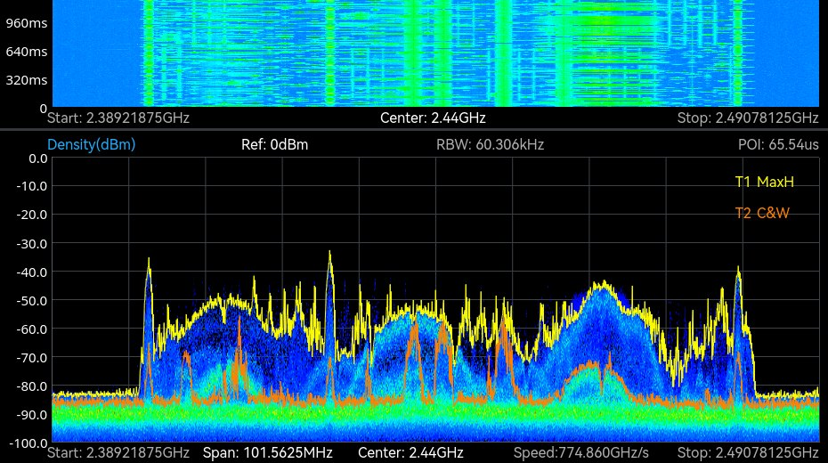
The ICX-FieldHawk receivers are real-time analyzers. Instead of sweeping, they process a wide span continuously, so the instrument sees the whole window all the time. The FPGA runs gapless, overlap-free FFTs across up to 100 MHz of analysis bandwidth, and the datasheet states the guarantee as arithmetic: with a 32-point transform at decimation 1 the frame rate is 3,906,250 per second and any event lasting 0.512 µs or longer is captured in full; at 2,048 points the guaranteed duration is 32.768 µs with finer frequency resolution (ICX-095, 200 and 400 tiers). The density display then separates the constant from the rare: a weak signal under a strong one appears as a fainter trace because it occurs less often.
Capture is armed by a trigger rather than by a watch. IQ Streaming mode acquires on multiple trigger methods, the external trigger input responds up to 500 times per second, and each capture runs into 128 Mbyte of built-in memory at up to 100 MHz bandwidth. A burst that fires once a minute is recorded at its trigger, then replayed and measured afterward, which turns a long watch into a stored event.
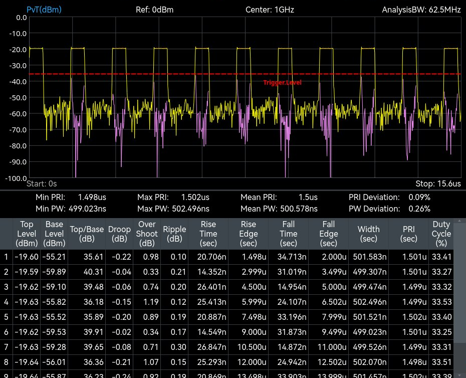
On top of the live view, the SpectraCore software adds Pulse Detection (option 72) and Digital Demodulation (option 71). The Pulse Detection screen tabulates each pulse: top and base level, rise and fall time, width, pulse repetition interval and duty cycle, with the minimum, maximum and mean PRI and width over the record, which is the measurement set radar characterization starts from. Digital Demodulation covers 2ASK, 2FSK, 4FSK, GMSK, BPSK, QPSK, 8PSK and 16 to 256 QAM for the communications side, so an operator moves from detection to identification on one instrument.
Which models and accessories fit
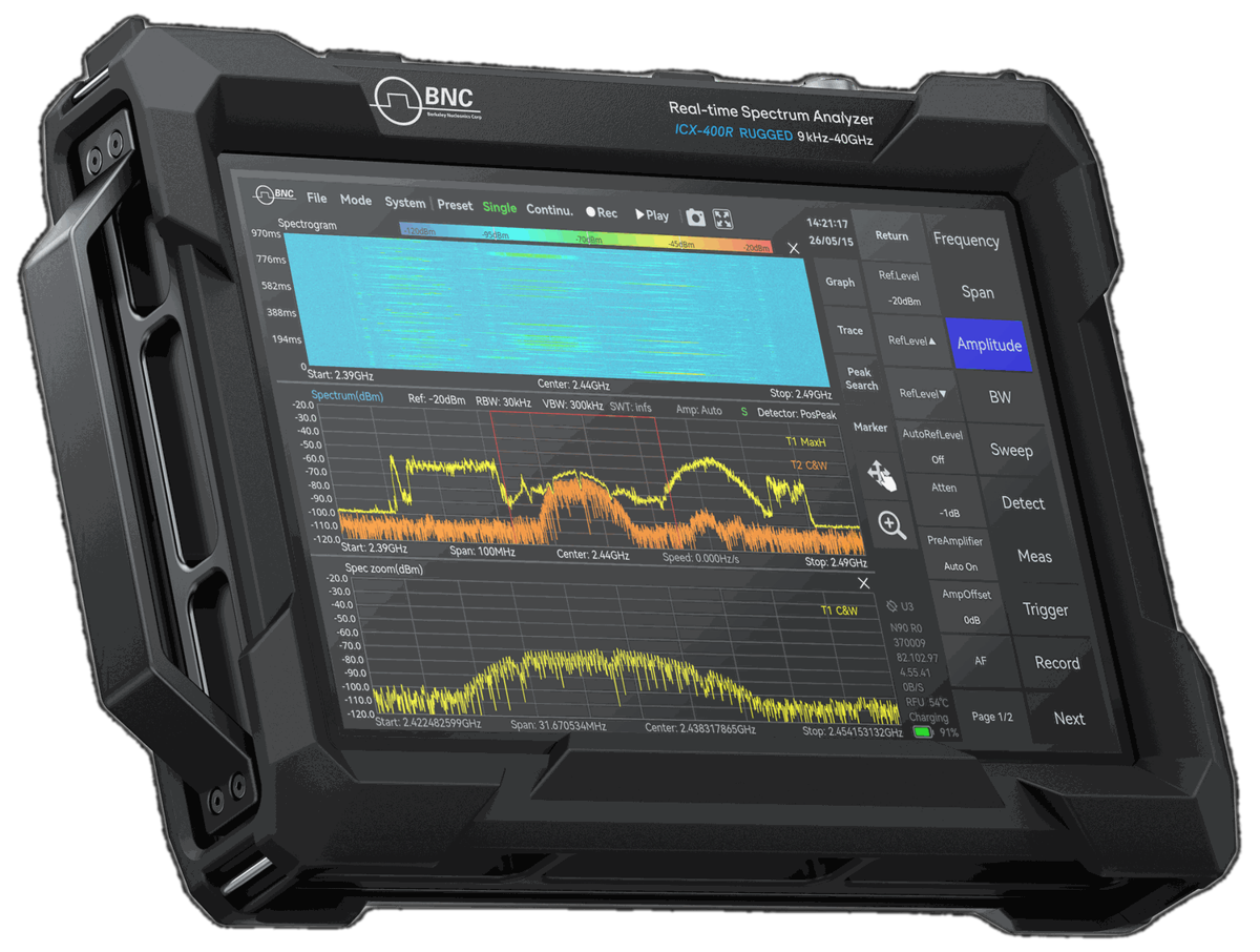
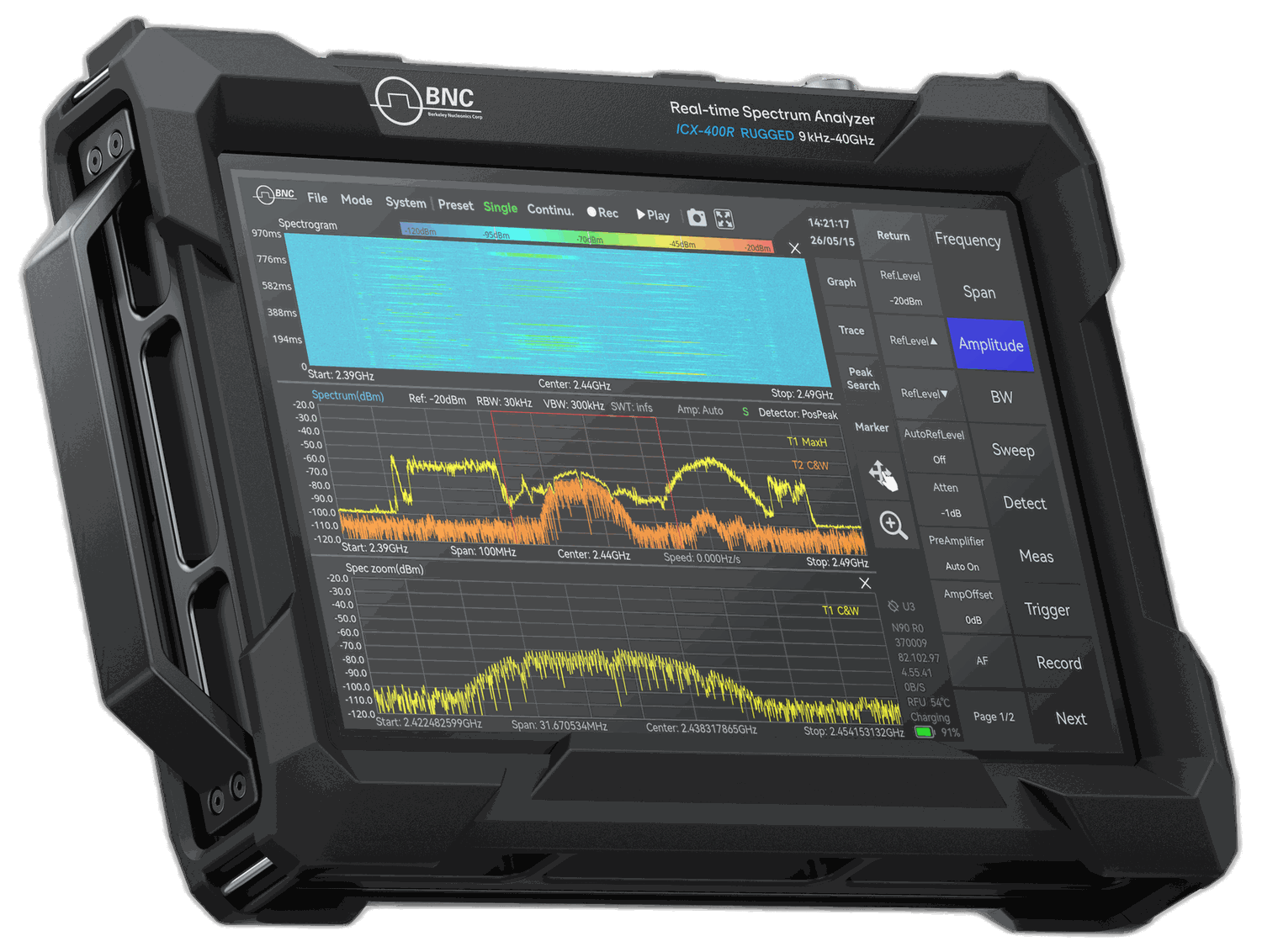
For dismounted and forward work, the recommended platform is the ICX-FieldHawk-R: the same measurement engine in an IP68 impact-protected chassis with corner bumpers, operating from 0 to 50 °C as standard and to -20 °C (T1, option 40) or -40 °C (T2, option 41). An instrument specified for the conditions on the day is the one that is in use rather than in its case.
Where the receiver feeds a larger system, the ICX-Series USB/LAN module (ICX-200U to 20 GHz, ICX-400U to 40 GHz) is the right tool. It integrates into SDR platforms, vehicle racks, automated test stations, and custom processing chains, exposing the same real-time engine through one API for C/C++, C#, Python, MATLAB, Qt and LabVIEW, with SCPI. At 40 GHz it reaches the microwave radar and satellite bands where aerospace work increasingly lives.
For directional work and threat geolocation, pair either receiver with the RFA-3100-N directional antenna. It covers 500 MHz to 10 GHz with 5 dBi typical gain, a front-to-back ratio above 15 dB and a 20 dB amplifier that can be bypassed, so an operator can take a bearing on an emitter and separate it from background traffic. Detection confirms that a signal exists; the antenna gives it a direction.
| Need | Recommended model | Why |
|---|---|---|
| Field and forward operations | ICX-FieldHawk-R | IP68 impact-protected chassis, temperature classes to -40 °C, USB PD power |
| ATE / SDR / rack integration | ICX-Series (ICX-200U, ICX-400U) | USB or LAN module to 20 or 40 GHz for test stations and embedded builds |
| Direction finding | RFA-3100-N | Directional gain for bearing and angle-of-arrival work |
Recommended configuration
A strong two-piece kit starts with the ICX-FieldHawk-R for field operations and an ICX-Series covering to 40 GHz for bench and rack integration, both running SpectraCore with 100 MHz analysis bandwidth, triggered IQ capture, Pulse Detection (option 72) and Digital Demodulation (option 71). Add an RFA-3100-N for directional sweeps and bearing. That pairing covers gapless wideband capture, triggered capture of short events, pulse parameter measurement and demodulation across radar and communications work.
Frequency coverage, real-time bandwidth, and onboard processing should be scoped to the signals you expect. Reach a Berkeley Nucleonics applications engineer at info@berkeleynucleonics.com or 800-234-7858.
For a quick question, chat with an engineer at berkeleynucleonics.com.