How to Measure Additive (Residual) Phase Noise of Amplifiers
Additive phase noise, the self phase noise a component adds as a signal passes through it, is one of the most useful things you can characterize when you are budgeting the noise of a system. This note walks through a single-channel additive phase noise measurement of an RF amplifier on the BNC 7000 Series, from the hardware setup through calibration to reading the final plot.
What additive (residual) phase noise is
Additive phase noise, also known as residual phase noise, is the self phase noise of a component that adds to an existing signal as the signal passes through it. Hence, the additive (residual) phase noise measurement is a valuable technique used to identify the phase noise contribution of a single component as part of a system design. This application note focuses on the single-channel additive phase noise measurement of an RF amplifier.
Introduction
One benefit of the 7000 Series is its capability to measure additive phase noise (also known as residual phase noise) of non-self-oscillating devices under test (DUT) such amplifiers, transmitters, mixers or prescalers. Although this can be done on a single channel; using a two-channel cross-correlation achieves the lowest phase noise.
Theory
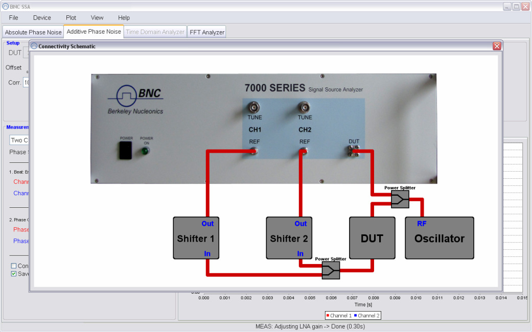
The single channel additive phase noise measurement works as shown below in the schematic diagram (Figure 2). A stimulus source is set to the desired frequency. The signal is split into two paths. One path is fed into the DUT input and the other path is fed into the REF input. In one signal path a phase shifter is inserted to allow phase adjustments between REF and DUT port. The 7000 SERIES compares the phase of the DUT and REF paths using a low noise phase detector. Using the phase shifter, the two signal paths are set to phase quadrature (90 degrees apart) at the phase detector. It can be shown that under perfect quadrature the correlated noise in the two signal paths (in particular phase noise from the stimulus source) is cancelled out.
Without any DUT, this measurement can be used to determine the setup phase noise floor. Adding the DUT into one signal path will add the DUT's phase noise and will be detected by the phase detector as deviation from quadrature (because it is only appearing in one signal path).
Note that in a single channel measurement, the phase shifter and the DUT can be located in either the DUT or REF signal paths. This gives some additional flexibility in the measurement setup.
Measurement setup and procedure
Additive noise measurements are typically at a lower noise level and are more difficult to perform than absolute phase noise measurements, requiring careful measurement setup and calibration. While the setup involves traditional microwave plumbing, the calibration can be tedious and prone to significant error. Berkeley Nucleonics's 7000 Series of phase noise analyzers addresses this problem by completely automating the calibration.
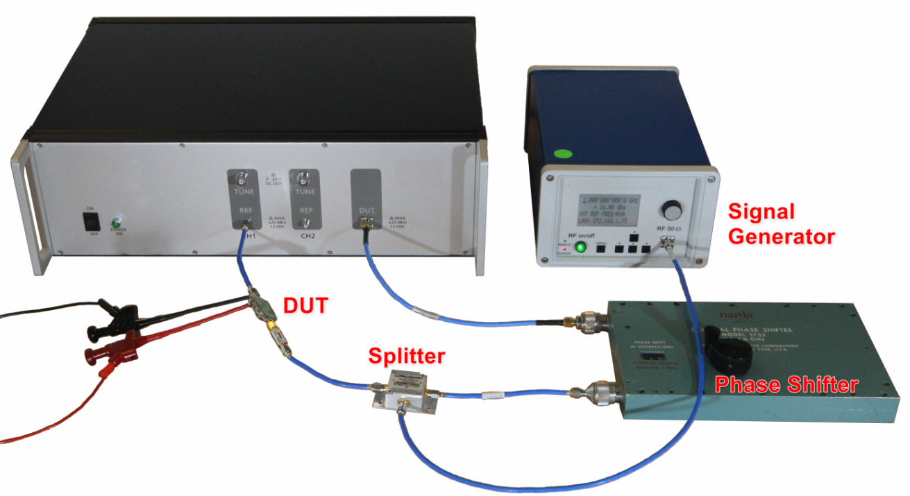
The hardware setup is shown below in Figure 2. In addition to the 7000 SERIES, a low phase noise signal source (in this case, the Model 845 20GHz signal generator is used), a power splitter and an electrically tunable or mechanical phase shifter are required.
The GUI setup
The measurement procedure can be split into two steps:
- A. Determine the measurement noise floor
- B. Perform the actual measurement on DUT
Determining the setup noise floor (step A) is especially important to ensure that the DUT noise is properly defined and is not influenced by other noise contributors. This step may be omitted if instrument noise floor is already known for the particular setup.
In step B, the DUT is added into one signal path and the measurement is repeated this time including the DUT.
Both steps require a full measurement to be performed; the only difference is that the DUT is replaced with a cable to measure the noise floor.
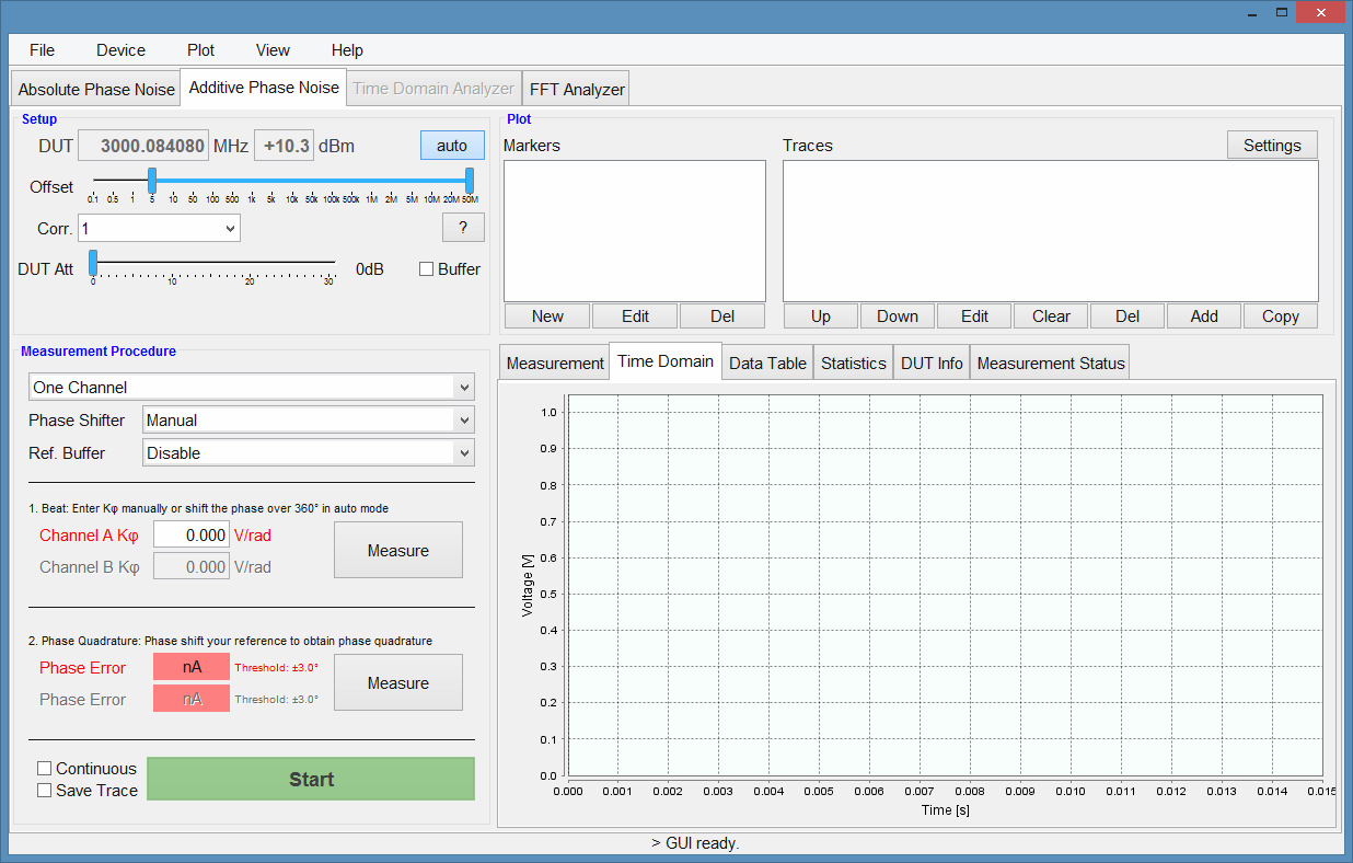
Starting the GUI, first the connection to the 7000 SERIES is established and the "Additive Phase Noise" tab is selected (see Figure 3). The next steps are:
- Select offset range and number of correlations. As in the absolute phase noise tab, select offset range and number of correlations. If additional signal attenuation or amplification is desired, then use the input attenuator/low noise amplifier stage.
- The DUT input power should be between +3 and +10 dBm. Above +10 dBm, the DUT input attenuator should be adjusted. Below +3 dBm, the input low noise amplifier may help to improve the measurement noise floor.
- The REF input should be operated between +9 and +17 dBm. Below +9 dBm the REF input low noise amplifier may be switched in to improve the noise floor.
- It is recommended to adjust the measurement setup if possible before using the buffer or attenuation options. For instance, the DUT can be placed either on the DUT or on the REF side which will affect the power levels at the DUT and RED input.
- To measure the input power of the signals, use the DUT input and press the "auto" button to start the frequency and power measurement of the attached signal.
- Select the "One Channel" measurement. The phase shifter can be chosen to be either a manually controlled phase shifter (as in this example), a voltage controlled phase shifter (via the 7000 SERIES tuning port), or a remote controlled digital phase shifter from Colby Instruments (Colby compatibility not yet implemented, ask Berkeley Nucleonics support for status).
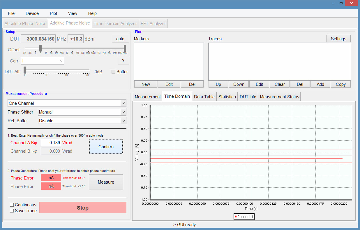
- Start the calibration. Once the setup is completed, the calibration procedure is started by clicking on the first "Measure" button. Using the phase shifter, the phase is now rotated continuously over 360 degrees to determine the phase detector constant (see Figure 4). Complete the calibration step by clicking on the corresponding "Confirm" button.
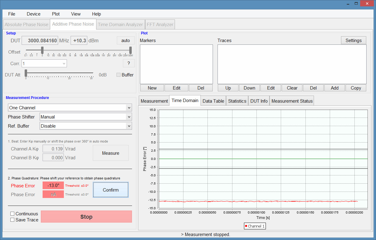
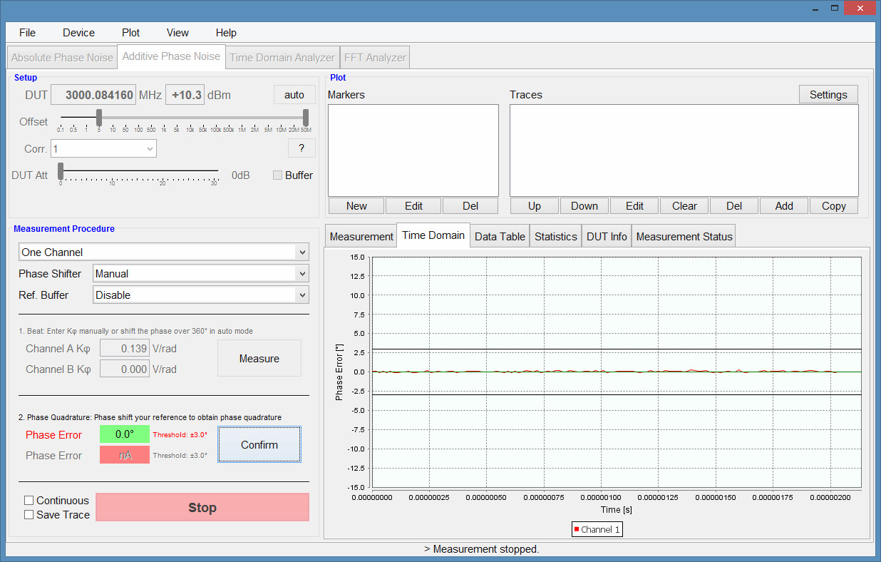
- Adjust to quadrature. In a next step, the signals at the phase detector are adjusted to quadrature (90° phase shifted in respect to each other) using the phase shifter (refer to Figure 5 above and Figure 6 below). Clicking on the second "Measure" button will continuously show the current phase error which has to be reduced to 0° by phase shifting the reference. Once the phase error is minimized, complete the calibration step by clicking on the second "Confirm" button.
- Start the measurement. Once the phase detector has near quadrature phases and is confirmed by the user, the "Start" button is enabled and the actual measurement can be performed (see Error! Reference source not found.) (verify) by clicking on the green "Start" button. The GUI will automatically switch to the phase noise plot and show the result after the measurement is finished.
Analyzing the result
Figure 7 below shows the measured instrument noise floor (as measured in step A) of the particular setup as the blue curve. Using a stimulus source of +16 dBm at 2 GHz, the setup noise floor is lower than -175 dBc/Hz for offsets above 10 kHz and below -140 dBc/Hz at 10 Hz offset. Using two channel cross-correlation, noise floors below -190 dBc/Hz can be achieved.
The measurement including the DUT amplifier is shown as the green curve.
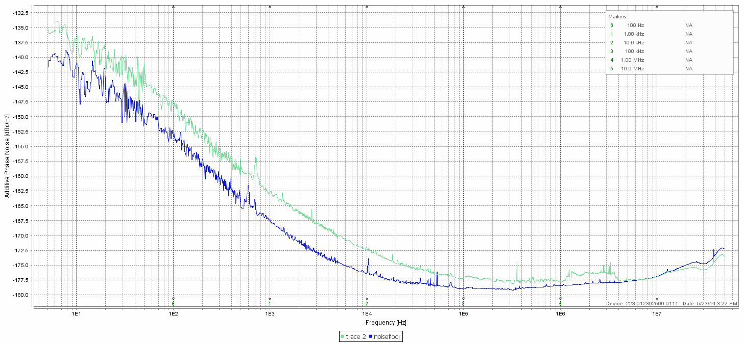
In Figure 7, the measurement including the DUT amplifier is shown as the green curve.
For offsets up 4 MHz, the DUT phase noise dominates the setup noise floor (i.e. shows a higher phase noise value), indicating that the measurement is dominated by the DUT noise. At higher offsets, the green trace reaches the setup noise floor. Only a cross-correlation measurement enables lower level measurements.
Conclusion
As shown in this application note, a simple procedure using the 7000 Series allows measurement of amplifier phase noise at very low phase noise levels. For lowest phase noise floors, the setup must be duplicated on a second measurement channel and cross-correlation must be applied.
Talk to an application engineer
If you are budgeting the additive phase noise of an amplifier, mixer, or other two-port device, our engineers can help you match a 7000 Series configuration to your frequency, power, and noise-floor targets. Request a quote or a demo and we will follow up with a setup tailored to your device under test. You can also reach us at info@berkeleynucleonics.com or 800-234-7858.
Ask now → Chat with our assistant and get an answer in seconds.