Temperature Sensitivity of Power Sensors
Temperature changes the performance of almost every electronic device, and it matters most when the device is part of a measuring instrument. RF and microwave power sensors validate test systems by measuring power accurately across frequency and level, and a conventional sensor's reading moves with its temperature: the measurements in this note show errors above 1.5 dB, which is more than 41 percent in power, at low levels. The usual remedy is to zero and calibrate the sensor before use, and again whenever the ambient temperature moves by about 5 °C.
That procedure rules conventional sensors out of several applications: a sensor embedded in a rack of test equipment to monitor a test point, a remote sensor in a harsh environment, and any unattended stream of measurements over hours or days, such as a strip chart.
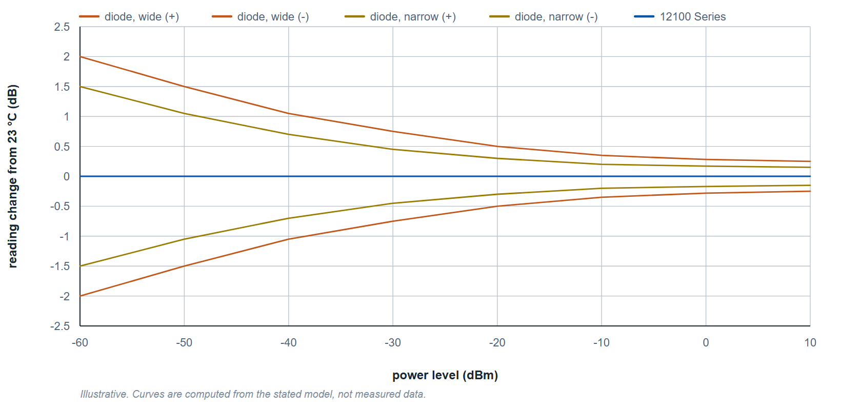
Figure 1 shows the pattern. As a typical diode sensor moves from 23 °C to either limit of its temperature range, its reading at low power changes by up to 2 dB in the illustrative envelope of Figure 1, and by more than 3 dB for one of the measured sensors in Figure 4, or the sensor stops reading. A 2 dB error is a 58 percent error in power. In the datasheet's measured trace at 1 GHz the Model 12100 Series reading holds within hundredths of a dB from 0 to 50 °C; the specification over temperature is in Table 1.
Zero and Calibration
The zero & cal process for traditional power sensors involves multiple disconnections from the test system measurement point or device under test and connections to an external calibration source. Zero and calibration correct offset and gain at the temperature at which they are run; they do not correct a temperature change that occurs afterward. Newer sensors that have an internal zero & cal capability and do not require an external calibration source will also exhibit sensitivity to temperature. In this case, the internal zero & cal is automatically performed periodically and not for each measurement. Additionally, the ability of a power sensor to adapt to changes in temperature is limited to how rigorous of a factory calibration was performed and the ability of the sensor to report its temperature. Figure 2 shows the measured sensitivity of a USB sensor with internal zero and no calibration step. At the lower power levels the error exceeds 1.5 dB, which is more than 41 percent in power.

The Model 12100 Series average power sensors need no zero and no calibration step. Each sensor is factory calibrated across its full operating temperature range, and in use it measures its own temperature with every power reading and applies the matching factory calibration factor, a patented method. The temperature uncertainty that results is specified in Table 1.
| Temperature (°C) | Specification | Typical |
|---|---|---|
| 40 to 55 | 2.5% | 0.5% |
| 30 to 40 | 0.5% | 0% |
| 20 to 30 | 0% | 0% |
| 10 to 20 | 0.5% | 0% |
| 0 to 10 | 2.5% | 0.5% |
Uncertainty is in percent of power: 0.5 percent is 0.02 dB and 2.5 percent is 0.11 dB. The datasheet's measured trace at 1 GHz holds within hundredths of a dB from 0 to 50 °C.
Sensor Design Categories
Power sensors fall into three common design categories: thermistor, thermocouple, and diode detector. For a thermistor detector, the RF power heats the detector changing its resistance thereby providing the power measurement. For the type using a thermocouple, the microwave power is absorbed by a load within the sensor and the temperature rise of the load is then measured by the thermocouple. The diode detector operates in its square law region where the DC component of the diode output is proportional to the square of the AC input voltage thus providing the power measurement.
Data collected from a thermistor sensor and several different models of diode sensors at hot and cold temperatures shows reading changes of up to 3.3 dB for the diode sensors and up to 20 dB for the thermistor sensor. The temperature extremes of specified operation were used to best illustrate the variability of the measurement from room temperature (23° C).
The thermistor sensor, where the measurement depends on measuring the heat dissipated in the device, is particularly sensitive. Figure 3 shows that below 0 dBm the thermistor reading departs from the room-temperature value by about 3 to 20 dB.

Figure 4 shows a composite of the temperature sensitivity data collected from five different diode sensors. Measurements were made at the extremes of their temperature ranges. Note that some sensors cease to operate at lower power levels of -50 or -60 dBm. The red trace shows the Model 12100 reading close to 0 dB variation at the same temperature extremes; its specified limit there is 2.5 percent (0.11 dB), as Table 1 shows.

The Model 12100 Advantage

The Model 12100 Series holds its reading over its operating temperature range without zeroing or calibration, to the uncertainty in Table 1. The sensor measures 1.51 by 1.51 by 3.95 inches, ships with the PowerEye software, is stable five minutes after power is applied, offers trigger input and output, and is available with Type-N, 3.5 mm, 2.92 mm, 2.4 mm and 1.85 mm connectors and as the WR-15 waveguide Model 12175.
For more information, visit the Model 12100 Series product page, or contact info@berkeleynucleonics.com or call 800-234-7858.