High-Energy Physics & Synthesizer Diagnostics
Precision instrumentation lives or dies on the quality of its reference signals. In a particle accelerator, the RF systems that bunch and steer the beam have to hold frequency and phase to extraordinary tolerances. A small drift in phase noise smears the beam. A frequency that hops when it should hold disrupts the timing that keeps a fill stable. The signals that report on all of this are clean, narrow, and unforgiving: the interesting behavior is often a faint sideband sitting close to a strong carrier, or a brief excursion that lasts only as long as a fault.
The same exacting standard applies on the bench. A voltage-controlled oscillator or a frequency synthesizer is judged by how quietly and how stably it produces a tone. Phase noise close to the carrier sets the limit on everything downstream, and a synthesizer that hops between frequencies has to settle fast and land clean. Measuring this means resolving a weak skirt next to a strong line, and watching a hop as it happens rather than reconstructing it afterward.
A swept analyzer looks at one slice at a time, so a frequency hop or a transient instability can occur entirely between sweeps. For an event that is short and a signal that is faint, the time between visits is the limit.
How the ICX-FieldHawk line solves it
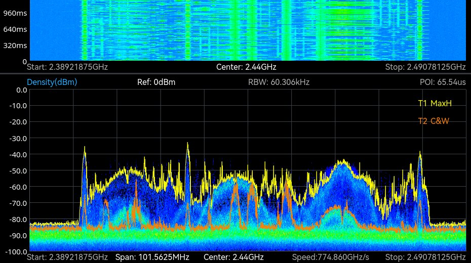
The ICX-FieldHawk receivers analyze in real time, holding the whole span under continuous observation rather than stepping across it. For beam diagnostics and synthesizer test alike, that means a frequency hop is captured as it happens and a transient instability leaves a visible trace instead of vanishing in a sweep gap: any event of 0.512 µs or longer is captured in full with a 32-point transform at decimation 1 on the 100 MHz tiers. The density display separates the steady carrier from the rare excursion, so a brief glitch in an otherwise stable signal stands out.
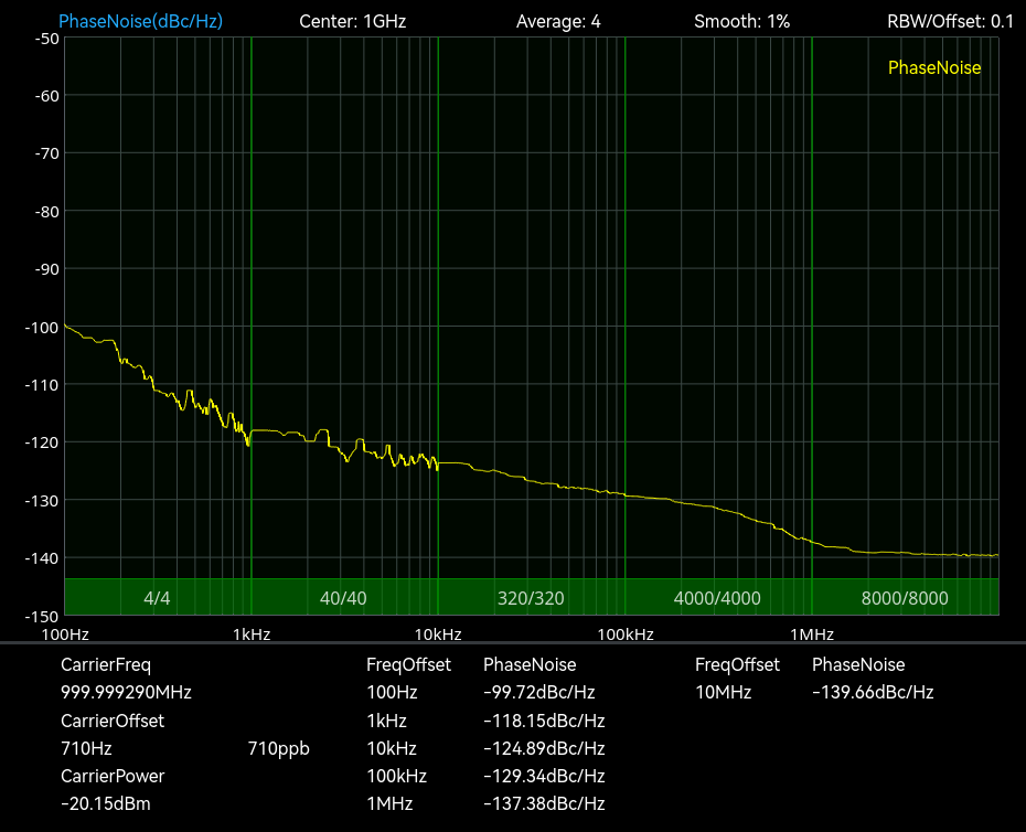
The SpectraCore software adds automatic phase-noise measurement at offsets from 1 Hz to 10 MHz with an automatic carrier search, so an engineer reads the carrier and the noise skirt directly instead of building the plot by hand. The limit is the analyzer’s own contribution, and the datasheets state it. On the ICX-045, 060 and 090 the measurement floor of that mode at a 1 GHz carrier is -120 dBc/Hz guaranteed (-124 typical) at 10 kHz offset and -136 (-139 typical) at 1 MHz. On the ICX-095, 200 and 400 tiers the analyzer’s own single-sideband phase noise at 1 GHz is -107.5 dBc/Hz at 10 kHz and -122.7 dBc/Hz at 1 MHz. A source quieter than those figures reads at the floor. That makes the mode a fast production check for VCOs and synthesizers above the floor; a reference oscillator or a low-noise synthesizer below it needs a dedicated cross-correlation phase-noise analyzer such as the Berkeley Nucleonics 7000 Series. A hop is captured as a spectrogram and as raw IQ at up to 125 MSPS, so the dwell sequence and the timing of each transition can be read from the record.
Every measurement is available through the API (C/C++, C#, Python, MATLAB, Qt, LabVIEW) and SCPI on Windows and Linux, so a phase-noise sweep or a hop capture can be scripted into a control-room logging chain or a production test without the front panel.
Which models and accessories fit

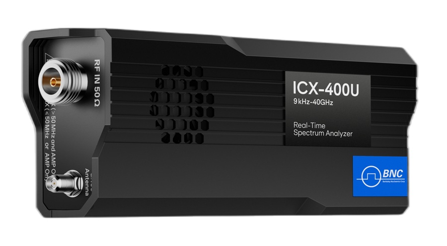
For lab and accelerator-facility work, the recommended platform is the ICX-Series USB core module. It integrates into a workstation, a control rack, or an automated synthesizer test station, exposing the full real-time engine and the automatic phase-noise tools through a programmable interface. That makes it straightforward to fold into an existing measurement chain or a scripted production test, with the ICX-200U covering to 20 GHz and the ICX-400U to 40 GHz.
For walk-up measurements at the rack, in the tunnel, or anywhere a fixed station does not reach, the ICX-FieldHawk handheld brings the same real-time analysis and phase-noise capability to the point of work. An engineer can verify a reference, check a hop, or chase an instability on the spot, then carry the result back for deeper analysis. Between the two, a facility covers both the scripted bench and the hands-on field check with one consistent measurement engine.
| Need | Recommended model | Why |
|---|---|---|
| Lab / facility / ATE integration | ICX-Series | Real-time engine with automatic phase-noise tools, programmable |
| Walk-up checks at the rack or tunnel | ICX-FieldHawk handheld | Same analysis and phase-noise capability at the point of work |
Recommended configuration
A strong diagnostics kit pairs the ICX-Series for bench, facility, and automated synthesizer test with the ICX-FieldHawk handheld for walk-up checks, both running SpectraCore with automatic phase-noise measurement, real-time spectrum, and frequency-hop capture enabled. That combination covers phase-noise screening above the stated floor, beam-stability monitoring, and hop timing, on a scripted bench and out at the rack.
Phase-noise floor, frequency coverage, and integration needs vary across accelerator and synthesizer work. A Berkeley Nucleonics applications engineer can scope the right configuration. Reach us at info@berkeleynucleonics.com or 800-234-7858.
For a quick question, chat with an engineer at berkeleynucleonics.com.