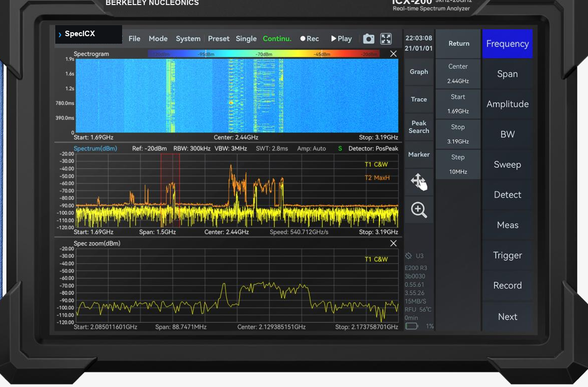
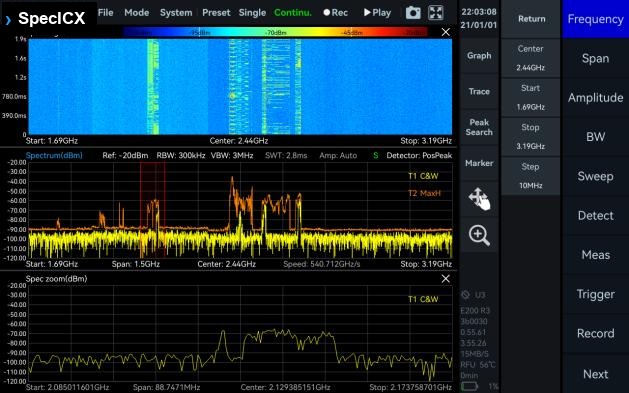
A portable real-time spectrum analyzer in a 10.1-inch touchscreen handheld. The ICX-FieldHawk covers 9 kHz to 40 GHz across six models, delivers up to 100 MHz of gapless analysis bandwidth, and sweeps up to 1 THz/s for fast field work and lab measurement.
The Berkeley Nucleonics ICX-FieldHawk is a handheld real-time spectrum analyzer built for solid RF performance away from the bench. The series offers frequency ranges from 9 kHz up to 4.5, 6, 9, 9.5, 20, or 40 GHz and an analysis bandwidth of up to 100 MHz: the 4.5, 6, and 9 GHz models ship with 50 MHz and take a 100 MHz option, and the 9.5, 20, and 40 GHz models ship with 100 MHz. Based on a fast FFT design, the series achieves a sweep speed up to 1 THz/s.
The instrument is equipped with a 10.1-inch full touch screen and an intuitive user interface that allows smartphone-like touch gestures. It weighs around 1.5 kg for easy carry and operation in the lab or the field.
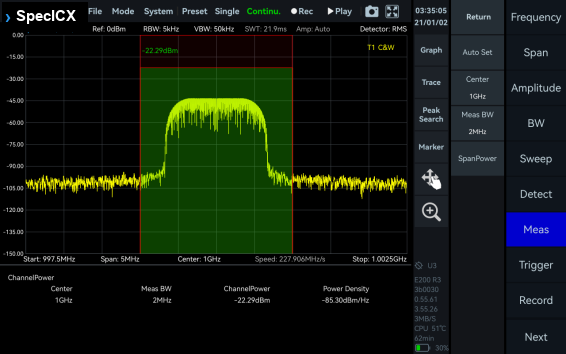
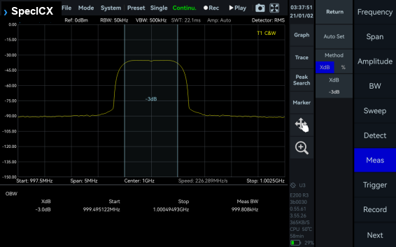
The ICX-FieldHawk comes standard with a variety of advanced measurement functions, including channel power, OBW, X dB bandwidth, harmonic measurement, SEM, AM/FM demodulation, and automatic phase noise analysis. The SpectraCore software adds spectrum, spectrogram, and historical trace views.
Highly compatible API interfaces support mainstream programming languages including C/C++, C#, Python, MATLAB, Qt, and LabVIEW. That makes secondary development straightforward and integration into larger systems clean. Talk to a Berkeley Nucleonics engineer about matching the right model to your application.
2Key Features
Ultra portable, flexible performance. A field-ready handheld that does not trade away RF measurement depth.
Up to 3 hours typical battery life (2.5 hours on the ICX-045/060/090) with external power expansion support for longer sessions.
Portable design. About 1.5 kg with a 10.1-inch multi-touch screen.
Frequency range 9 kHz to 4.5 / 6 / 9 / 9.5 / 20 / 40 GHz across the ICX-045, ICX-060, ICX-090, ICX-095, ICX-200, and ICX-400 models.
Up to 100 MHz analysis bandwidth with gapless, overlap-free real-time FFT. 50 MHz standard with a 100 MHz option (opt. 50) on the ICX-045/060/090.
1 GHz DANL to -168 dBm/Hz (typ.) on the ICX-045/060/090, and below -160 dBm/Hz across the family, for low-level signal work.
1 GHz phase noise down to -110 dBc/Hz at 10 kHz offset (ICX-045; model dependent across the family).
Superheterodyne front end with up to 14 preselector filter bands and IF and image rejection above 95 dBc (typ.) on the ICX-045/060/090.
Integrated GNSS on the ICX-045/060/090, supporting frequency calibration via GNSS.
Standard SCPI protocol support for remote control and automation.
3Models & Frequency Range
Six models share the same 10.1-inch handheld platform. They differ in upper frequency limit, RF input connector, and analysis bandwidth fit: the ICX-045, ICX-060, and ICX-090 ship with 50 MHz and take a 100 MHz option, and the ICX-095, ICX-200, and ICX-400 ship with 100 MHz.
Model
Frequency range
RF input connector
Analysis bandwidth
ICX-045
9 kHz to 4.5 GHz
N (F), impedance 50 Ω
50 MHz (100 MHz opt. 50)
ICX-060
9 kHz to 6 GHz
N (F), impedance 50 Ω
50 MHz (100 MHz opt. 50)
ICX-090
9 kHz to 9 GHz
N (F), impedance 50 Ω
50 MHz (100 MHz opt. 50)
ICX-095
9 kHz to 9.5 GHz
N (F), impedance 50 Ω
100 MHz
ICX-200
9 kHz to 20 GHz
N (F), impedance 50 Ω
100 MHz
ICX-400
9 kHz to 40 GHz
2.4 mm (M), impedance 50 Ω
100 MHz
4Operating Modes
The ICX-FieldHawk offers main operating modes including Standard Spectrum Analysis, IQ Streaming, Power Detection, Real-Time Spectrum, Phase Noise Measurement, and Harmonics Analysis. Digital Demodulation is available as an option. On the ICX-045/060/090, Mapping mode (GPS-referenced heat maps for radio monitoring and interference analysis) is additionally standard, and EMI Pre-Compliance Measurement (opt. 74, CISPR 16-1-1 detectors, bandwidths, and limit lines — see section 11) is available as a software option.
Standard Spectrum Analysis
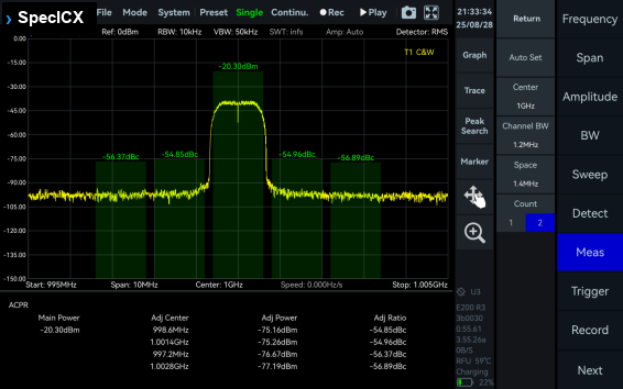
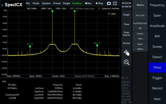
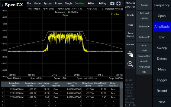
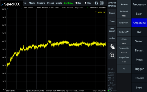
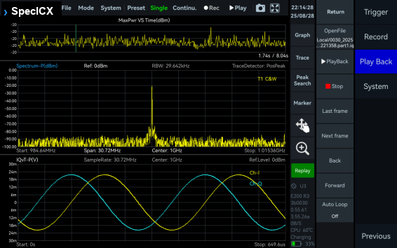
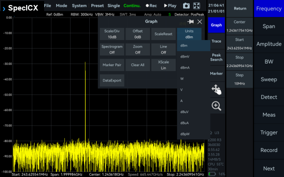
This mode provides a wide range of measurement functions, including full-span spectrum sweep, channel power, OBW, ACPR, IM3, and SEM. It also supports spectrum recording and playback. Combined with auxiliary tools such as signal tracking, peak table, and amplitude correction, it delivers a one-stop platform for comprehensive spectrum check.
Standard Spectrum Analysis
IQ Streaming Analysis
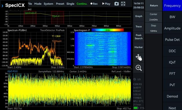
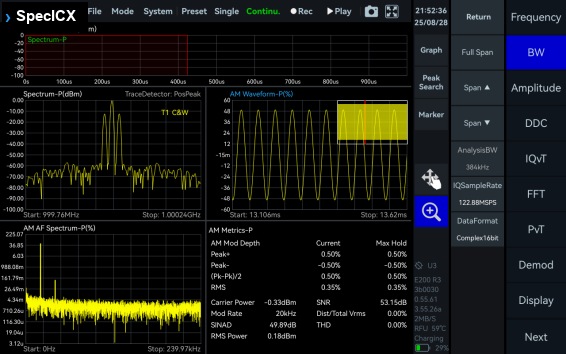
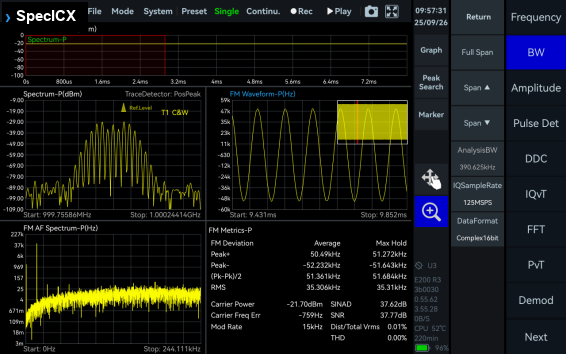
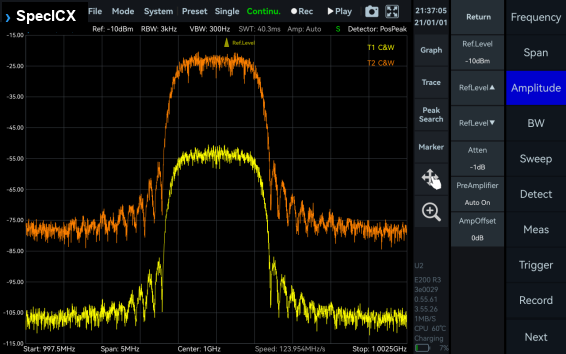
This mode supports up to 100 MHz analysis bandwidth and allows IQ data acquisition through multiple trigger methods. It provides IQ time-domain waveform display, spectrum and spectrogram views, AM/FM demodulation, and digital down-conversion (DDC).
IQ Streaming Analysis
Power Detection Analysis
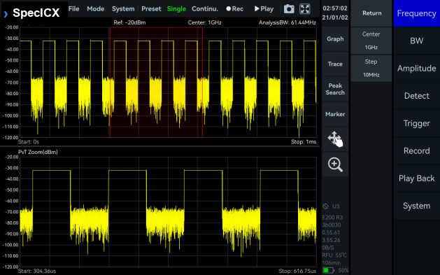
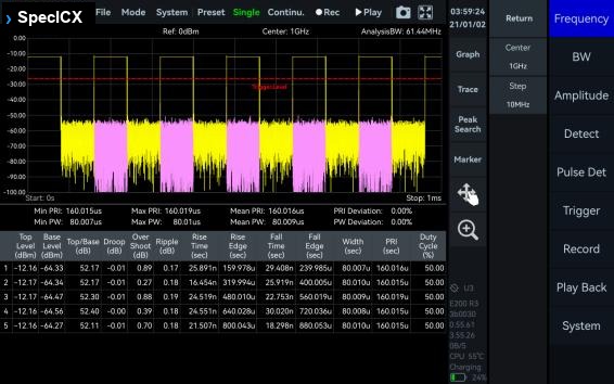
This mode enables detection and analysis of time-domain signals within the analysis bandwidth. It suits applications focused on in-band power-versus-time relationships, such as pulse signal measurements.
Power Detection Analysis
Real-Time Spectrum Analysis
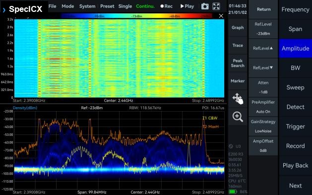
This mode is powered by a high-speed FPGA-based FFT engine. With strictly gapless and overlap-free FFT, it achieves true real-time monitoring across the full bandwidth.
Real-Time Spectrum Analysis
Digital Demodulation (option)
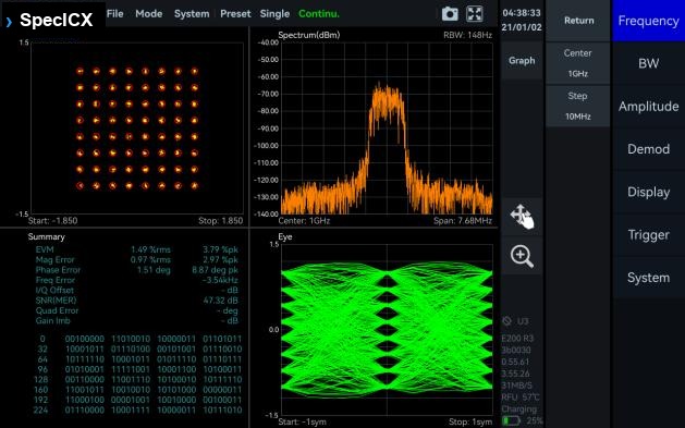
This mode supports 2ASK, 2FSK, 4FSK, GMSK, BPSK, QPSK, 8PSK, 16QAM, 64QAM, 128QAM, and 256QAM signals.
Digital Demodulation (option)
Harmonics Analysis
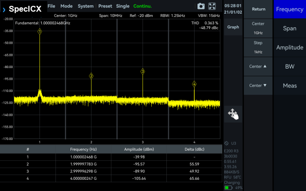
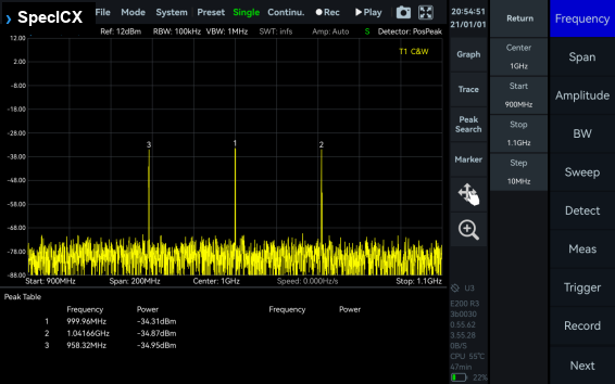
This mode supports detection and measurement of up to 10 harmonic components, including harmonic peaks, harmonic channel power, and total harmonic distortion.
Harmonics Analysis
Phase Noise Measurement
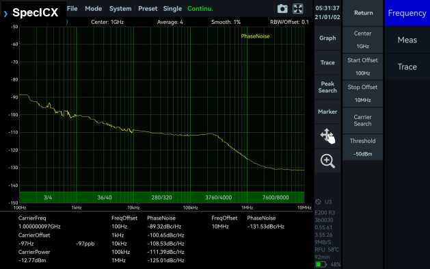
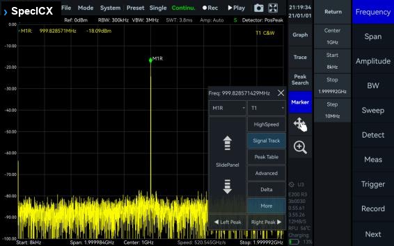
This mode supports offset ranges from 1 Hz to 10 MHz for evaluating carrier phase stability. With the built-in automatic carrier search function, the software can quickly locate the target carrier without manual adjustment.
Phase Noise Measurement
5Main Functions
A standard set of measurement and utility functions runs on every ICX-FieldHawk. Pulse Detection and digital demodulation are software options.
Channel PowerOBW
ACPRIM3
SEMAM Demodulation
FM DemodulationPulse Detection (option)
Antenna FactorAmplitude Offset
Signal TrackPeak Table
Data Record and PlaybackMultiple Unit Display
6Frequency & Spectrum Purity
Frequency
Parameter
ICX-045 / ICX-060 / ICX-090
ICX-095 / ICX-200 / ICX-400
Reference clock
Internal or external; manual correction or GNSS calibration is available
Internal or external
Frequency accuracy
≤0.5 ppm, manual correction is available
TCXO (std.): <1 ppm; OCXO (opt01): <1 ppm; manual correction is available
FFT engine is implemented in FPGA. Frame compression and trace detection are supported. No missing samples between FFT frames. FFT frame update rate = 10^9 ns / (N × D × min. time resolution); POI = 2 × N × D × min. time resolution, for FFT points N (4096, 2048, 1024, 512, 256, 128, 64, 32) and decimate factor D (1, 2, 4, 8...). Typical: N = 4096, D = 1 gives 15,258 times/sec (std.) or 30,517 times/sec (opt. 50) and 131.072 us (std.) or 65.536 us (opt. 50) POI; N = 32, D = 1 gives 1,953,125 times/sec (std.) or 3,906,250 times/sec (opt. 50) and 1.024 us (std.) or 0.512 us (opt. 50) POI.
Max. analysis bandwidth
50 MHz; 100 MHz with opt. 50
Window function
B-Nuttall, Flat-top, LowSideLobe, Rectangle, Kaiser
FFT engine is implemented in FPGA. Frame compression and trace detection are supported. No missing samples between FFT frames. FFT frame update rate = 10^9 ns / (N × D × 8 ns); POI = 2 × N × D × 8 ns, for FFT points (2048, 1024, 512, 256, 128, 64, 32) and D the decimate factor (1, 2, 4, 8...). Typical: N = 2048, D = 1 gives 61,035 times/sec and 32.768 us POI; N = 32, D = 1 gives 3,906,250 times/sec and 0.512 us POI.
Max. analysis bandwidth
100 MHz
Window function
B-Nuttall, Flat-top, LowSideLobe
RBW
14.73 MHz to 3.59 kHz (Flat-top); 7.81 MHz to 1.90 kHz (B-Nuttall); 13 grades for each window type
Amplitude resolution
0.75 dB
9IQ Recording
Parameter
ICX-045 / ICX-060 / ICX-090
ICX-095 / ICX-200 / ICX-400
Burst recording bandwidth
Maximum 50 MHz; 100 MHz with opt. 50. The built-in memory depth is 128 Mbytes.
Maximum 100 MHz. The built-in memory depth is 128 Mbytes.
Ambient temp. 0 to 40 °C: 5 to 75%; ambient temp. > 40 °C: 5 to 45%
Packaging and accessories
Protected main unit ×1, power adapter ×1, power cord ×1, lanyard ×1
Specification conditions. Values apply under the following conditions: (1) start up and warm up for 10 minutes; (2) ambient temperature 25 °C (core temperature 50 °C for the ICX-095/200/400); (3) standard spectrum analysis mode with spurious rejection standard on (ICX-095/200/400); (4) necessary heat dissipation is provided so the ambient and core temperatures stay within the rated range at the same time; (5) for the ICX-045/060/090, typical and nominal values are not guaranteed and do not include measurement uncertainty, and specifications may vary with hardware and software versions; (6) for the ICX-095/200/400, sweep speed and display average noise level test conditions are MCU 0.55.57, FPGA 0.55.22, API 0.55.61.
11Options
Code
Description
Type
Applies to
01
Built-in OCXO reference clock
Built-in hardware
ICX-095 / ICX-200 / ICX-400
05
Internal high precision GNSS
Built-in hardware
ICX-045 / ICX-060 / ICX-090
16
0 Hz start frequency
Built-in hardware
ICX-045 only
50
100 MHz analysis bandwidth
Built-in hardware
ICX-045 / ICX-060 / ICX-090
60
4.5 GHz tracking generator
Built-in hardware
ICX-045 only
61
6 GHz tracking generator
Built-in hardware
ICX-060 only
62
9 GHz tracking generator
Built-in hardware
ICX-090 only
34
External omnidirectional antenna, 400 MHz to 8000 MHz, gain < 2 dBi
Accessory
All models
35
External active directional antenna, frequency range 0.5 to 10 GHz, gain < 5 dBi (amp off); < 25 dBi (amp on)
Accessory
All models
71
Basic vector modulation / digital demodulation analysis
Software
All models
72
Pulse detection and analysis
Software
All models
74
EMI pre-compliance measurement: CISPR 16-1-1 compliant Peak, Quasi-Peak, Average and RMS detectors; CISPR-standard resolution bandwidths by band; a preloaded FCC Part 15 / CISPR 11, 22, 32 / IEC limit-line library; automated pass/fail margin analysis
Software
ICX-045 / ICX-060 / ICX-090
EMI Pre-Compliance Measurement (opt. 74)
Option 74 turns the ICX-045/060/090 into a CISPR-shaped pre-compliance bench without leaving the analyzer's own hardware. Detectors, bandwidths, and limit lines are matched to CISPR 16-1-1 so a bench scan tracks a chamber result rather than approximating it; SpectraCore automates the sweep sequence and flags any point that crosses the selected limit line.
Parameter
Detail
Detectors
Peak, Quasi-Peak, Average, RMS — run in parallel, no repeated scans per detector
Preloaded FCC Part 15 (Class A/B), CISPR 11, CISPR 22, CISPR 32, and IEC limit lines, with automated margin/pass-fail analysis against the selected line
Sweep workflow
Smart segmented sweeps across configurable bands; one-touch automated sequence (initial peak scan, automatic peak finding, Quasi-Peak/Average final measurement)
Independent publications citing this instrument, indexed by Bioz. Citation
counts and Bioz Stars ratings are shown live and update as new papers are indexed.
 Powered by Bioz