Optimal Low Noise Floors Using External References
Measuring the phase noise of very low noise reference sources can take hours on internal references alone. This technical note shows how the BNC 7000 Series PNT signal source analyzer uses external tunable references to reach lower instrument noise floors close to the carrier while cutting measurement time from hours to minutes.
Introduction
Using the PNT with cross-correlator and external references provides the benefit of faster measurement speed when measuring ultra-low single sideband (SSB) phase noise of devices under test (DUT). When using BNC's PNT signal source analyzer, the choices are:
- Standard internal references
- Option LN: close to carrier ultra low noise internal references
- Voltage tunable external references
Figure 1 below illustrates the phase noise sensitivity of the PNT for a single correlation (16 sec measurement time) for a 10 MHz DUT signal. The phase noise sensitivity indicates how low at a given offset from the carrier the DUT phase noise can be to be measured accurately. A DUT having a phase noise below the phase noise sensitivity requires either additional correlations (increasing measurement time) or cannot be measured at all.
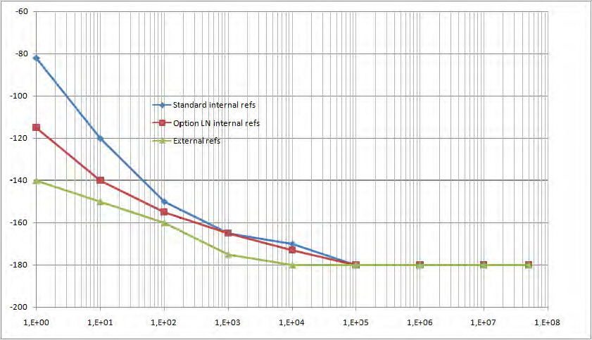
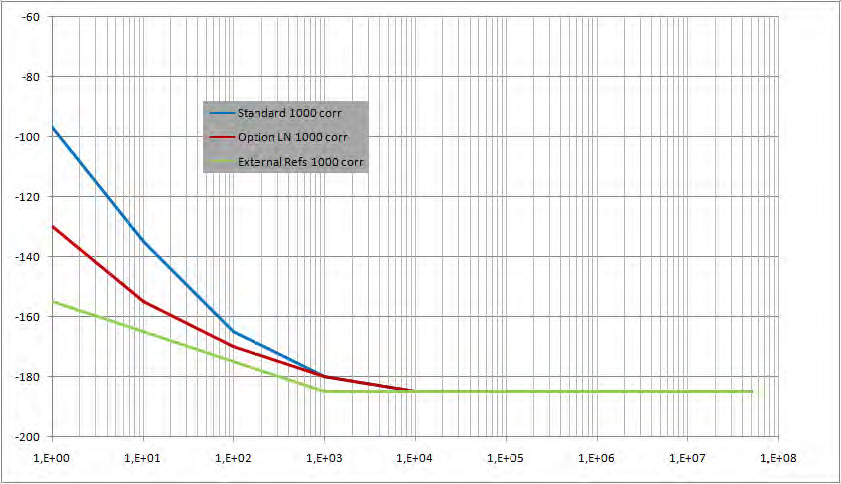
Figure 2 below shows the phase noise sensitivity after 1000 correlations: approximately 5 hours of measurement time. In this example, a 10 MHz low phase noise OCXOs with an expected phase noise of around -105 dBc/Hz at 1 Hz offset is to be measured. It becomes very apparent that after 1000 correlations, it will be difficult to measure such a device with standard internal references.
The Limitations of Standard Internal References
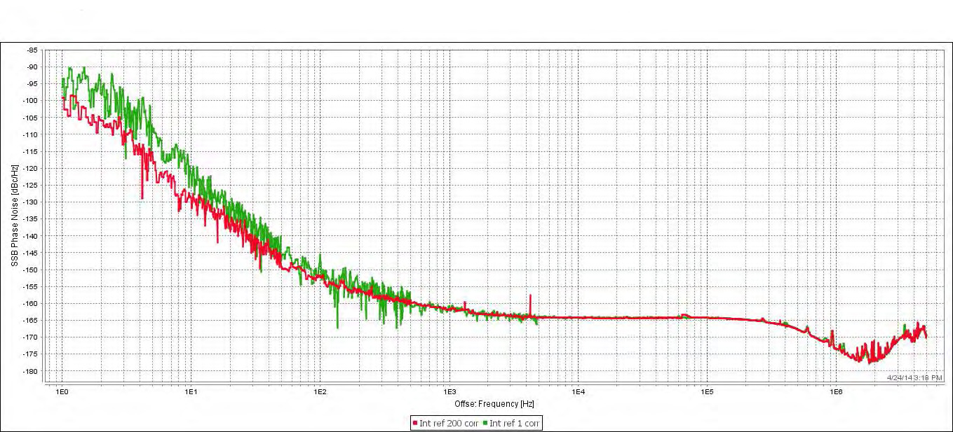
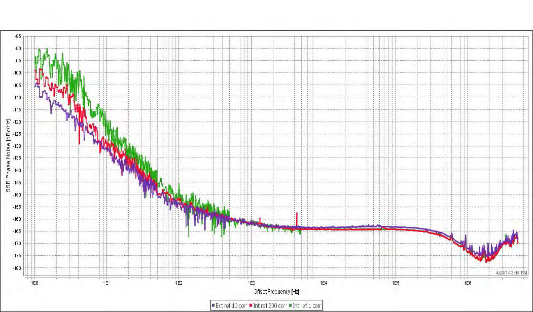
Figure 3 below shows the corresponding results after 1 correlation (green trace) and 200 correlations (red trace). For offsets 100 Hz and more the traces are identical. However, for offsets below 100 Hz the measurement is limited by the phase noise sensitivity of the PNT using standard internal references. Even after 200 correlations and 1.5 hours measurement time, the 1 Hz offset has not reached the expected value. Additional correlations and hours of measurement time is needed to obtain the actual result.
The Measurement Setup Using External References
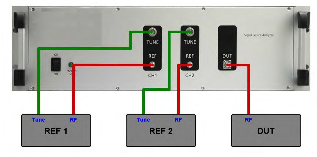
Alternatively, external references can be used that result in a substantially lower phase noise sensitivity at low offset frequencies. The block diagram of the measurement setup is shown below in Figure 4. Two 10 MHz OCXOs have been used as external tunable references. Both references shown here are through hole mounted test fixtures, and are supplied using the optional two low-noise internal supplies of the PNT. Each reference OCXO output is connected to the RF IN port of one of the PNT reference inputs, and each tuning port of the OCXO is connected to the corresponding tuning output port of the PNT. Therefore, the external references are fully controlled (biased, and tuned) via the PNT. The DUT signal is fed into the DUT port.
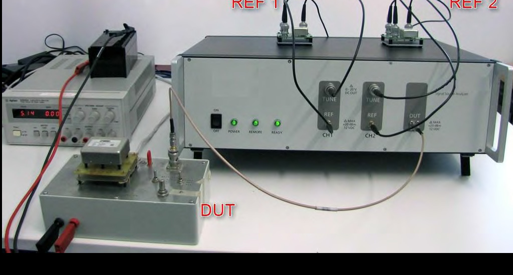
The actual measurement setup is shown below in the photograph in Figure 5.
The GUI Setup
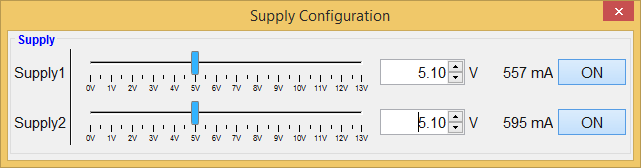
In the PNT GUI, the setup is straightforward. First, and only if desired, enable low-noise internal power supplies to power the external references. As shown below in Figure 6, in the Supply Configuration menu both supplies have been enabled and set to 5.1V and supply a current of more than 550 mA per channel during startup of the OCXO. Alternatively, the external references may be powered from external power supplies.
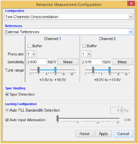
Next, the external references require a short calibration sequence of the external references to determine the tuning constant. In the Advanced Measurement Configuration menu, the tuning voltage range is set for each channel. In this case, a tuning range from 0 to +10 V is used. The Meas button then executes the calibration measurement. In this example, the calibration reveals respective 2.60 Hz/V and 2.57 Hz/V tuning sensitivities on the two channels.
The Measurement Results
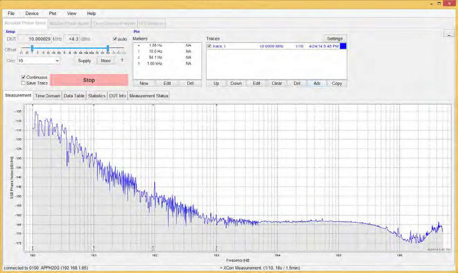
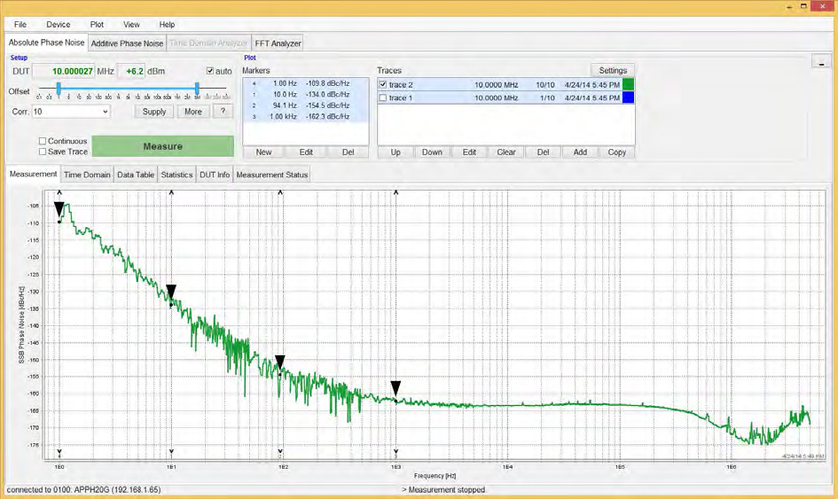
Once the calibration is completed, a click on the measurement button starts the measurement. In this example, the offset range is set from 1.0 Hz to 5.0 MHz and a total of 10 correlations. Figure 8 below shows the phase noise trace after the first correlation and Figure 9 the same after 10 correlations are completed. Comparing the results after 1 resp. 10 correlations shows a very good agreement. The longer measurement time for 10 correlations just leads to a "smoother" trace.
Finally, the measurement results using internal and external results are compared below in Figure 10. As expected, measurements using internal references (green trace after 1st correlation, red trace after 200 correlations) are in exact agreement with the purple trace (external references, 10 correlations) for offsets larger 100 Hz. For offsets below 100 Hz, using external references yield the correct result after just a few correlations.
Conclusion
In conclusion, the PNT offers great flexibility in configuring your measurement to the required performance level.
For most phase noise measurement applications, the use of the standard configuration with the internal references is the ideal choice providing easy to use reliable measurements.
For measurements of very low phase noise DUTs (especially close to the carrier below 10 Hz offset), the low-noise option of the internal references (option LN) or external references will offer lower instrument noise floors and substantially reduced measurement times.
With the help of the PNT GUI, the setup and calibration of external references is greatly simplified, offering an alternative way to perform ultra-low phase noise measurements in short amount of time.
Talk to an application engineer
If you are measuring ultra-low phase noise sources and want to reach the lowest instrument noise floor in the least measurement time, our engineers can help you configure the right reference option for your DUT. Request a quote or a technical consultation and we will match a PNT configuration to your requirement. You can also reach us at info@berkeleynucleonics.com or 800-234-7858.
Ask now → Chat with our assistant and get an answer in seconds.