The Mission
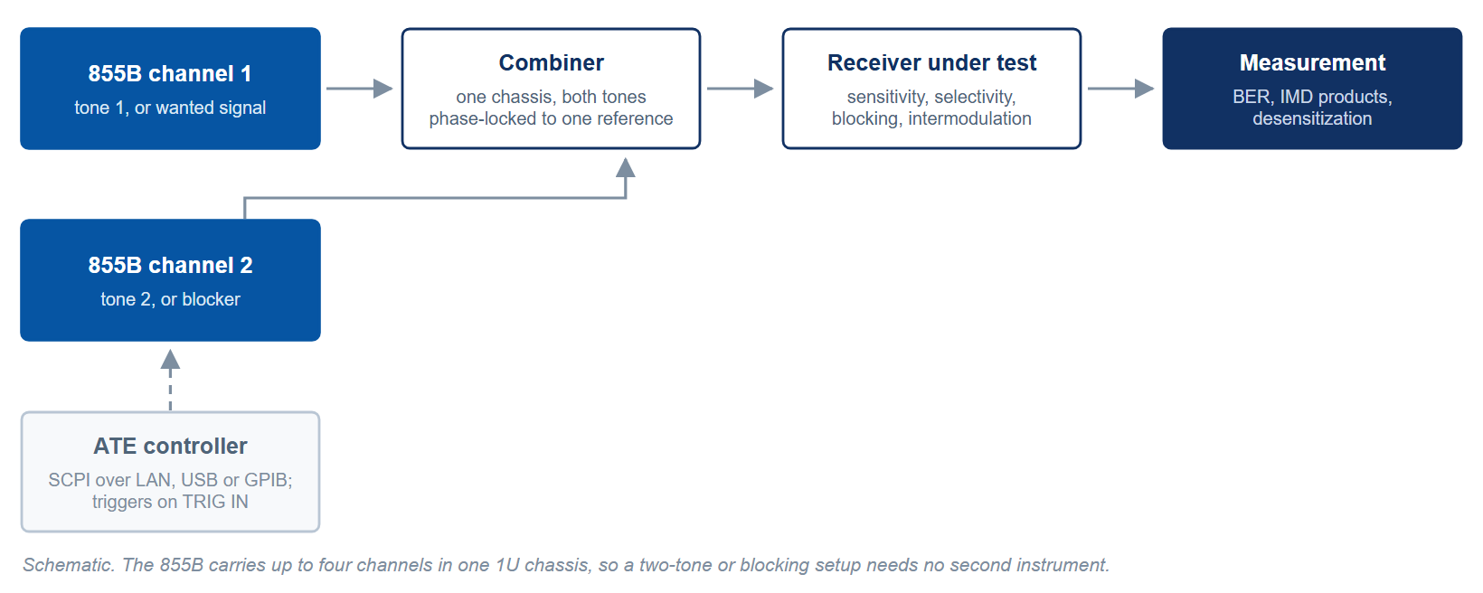
Throughput is the governing figure in automated test. A receiver-test or production ATE rack measures sensitivity, selectivity, blocking, and intermodulation across many frequencies and many units, often around the clock. The signal source has to step through test points quickly, present more than one tone when an interferer or blocker is required, and answer cleanly to a remote controller without manual intervention.
The Challenge
Slow frequency switching is dead time, and dead time multiplied across thousands of test points is lost capacity. Receiver tests such as two-tone intermodulation and blocking need two or more sources, ideally in one chassis to save rack space. And every function has to be reachable over a remote interface, because a production line runs under a remote controller. Speed, channel count, and clean programmatic control all have to come together.
Recommended Berkeley Nucleonics Solutions
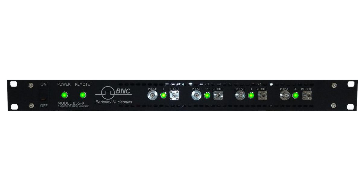
The Model 855B is built for this role: 1 to 4 phase-coherent channels in 1U, up to +25 dBm of output power (100 MHz to 6 GHz), and 3 GHz clock input and output ports for locking units together into larger multi-tone systems. For the fastest stepping, the Model 825-M reaches 5 µs switching with Option FS, which also adds a Fast Control Port for streamed frequency and amplitude updates, with up to four phase-coherent channels in 1U (825-M-20-X).
The Model 845 brings full modulation and a 100 kHz to 26 GHz span, with the board-level Model 845-OEM for tightly integrated test stations, while the Model 835 offers a 9 kHz to 6.1 GHz channel for sub-6 GHz receiver work at about 12 W. Figure 1 shows what the per-point switching time costs over a long sequence.
The arithmetic is direct. A 10,000-point list on the 825-M with Option FS spends 10,000 × 10 µs, or 100 ms, switching at the sweep-mode figure (50 ms if each point is set as a CW command at 5 µs); without the option the same list spends 5 s at 500 µs, or 2 s at the 200 µs CW figure. On the 855B the TRIG OUT port carries a signal-valid mode that marks when the output is valid at each point, and the external trigger input adds 5 ns latency and 10 ns uncertainty, so the controller can start the receiver read from that edge rather than from a fixed delay chosen for the worst case.
Why It Works
Multiple coherent channels in one chassis collapse two-tone and blocking setups into a single instrument, saving rack space and cabling. Fast-switching options cut the per-point dead time to microseconds, so the ATE spends its time measuring rather than waiting. Every model is fully remote-controllable, and the 845-OEM board lets the source be built into a custom test station instead of occupying a bench.
Getting Started
Berkeley Nucleonics applications engineers help match the right source, channel count, and options to your test plan. Tell us your frequency span, switching budget, and channel needs, and we will recommend a configuration and arrange a demo.
Contact info@berkeleynucleonics.com or call 800-234-7858. Browse the full family on the RF & Microwave Signal Generators documentation page.