
High-Voltage Test & Detector Biasing
Two very different jobs share the same requirement: a clean, stable DC high voltage that does exactly what it is set to do. The first job is test. High-voltage component testing and semiconductor characterization apply a known voltage and read a small response, so any noise or drift in the source shows up directly in the measurement. The second job is biasing. Photomultiplier tubes, solid-state and gas detectors, and accelerator electrodes need a bias that holds steady, because the gain of a PMT and the field at an electrode depend on it. In both cases the supply is part of the instrument, and its ripple and stability set the floor on what the rest of the system can achieve.
Berkeley Nucleonics, through its Directed Energy Division, supplies DC high voltage from 600 V detector-bias classes to 300 kV for high-voltage test, in three variants of the PNC series that differ in precision, power and input phase.
The challenge
The defining requirement is a quiet, steady output. In a detector, ripple on the bias rail rides straight through to the signal, so a PMT or a semiconductor detector reading low-level events needs a bias with ripple measured in parts per million, not percent. In a test setup, drift does the same damage as ripple over a longer time: a characterization that takes minutes carries any wander in the applied voltage into every point after the first, so the source has to hold its setpoint against time, temperature, and changing load. Very high voltage sharpens these demands, because the same fractional ripple is a much larger absolute disturbance: 0.01 percent peak to peak of 300 kV is 30 V.
Protection is the other half of the problem. High-voltage test exists to find the point where something breaks down, which means the supply will face arcs, flashovers, and dead shorts as a normal part of the work. It has to survive a short circuit without damage and respond cleanly, and where a load can store or return energy it has to tolerate reverse voltage rather than fail. And because these supplies sit inside automated benches, they need clean analog control so a test executive can program the voltage and read it back as part of a sequence.
The BNC approach
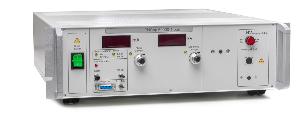
The DEI high-voltage supplies are built for regulation first. The PNC series covers 600 V to 300 kV at up to 2 kW, with ripple of 0.01 percent peak to peak of nominal voltage (±50 mV) and 8-hour stability of 0.01 percent. The high-precision PNChp tightens ripple and 8-hour stability to 0.001 percent (10 ppm) and the temperature coefficient to 0.001 percent per kelvin, and is available across most of the PNC model grid. The PNC3p runs from a three-phase 400 V input and delivers up to 6 kW at up to 60 kV. For a sensitive detector or a precision characterization bench, ripple and drift are the specifications that decide the choice.
Stability is what separates a usable bias from a noisy one. A photomultiplier gain rises steeply with applied voltage (Figure 1), so a small wander on the rail turns into a larger wander in gain, and drift over the course of a long count smears the result. For a tube with gain proportional to V7, the PNChp's 0.001 percent 8-hour stability corresponds to a gain drift of about 0.007 percent, and the standard PNC's 0.01 percent to about 0.07 percent. The same stability serves a characterization sweep, where the value of the measurement rests on the applied voltage being what the instrument reported when each point was taken.
Protection is part of the design. The PNC output is continuous short-circuit proof and reverse-voltage proof, so the failure of a device under test does not become the failure of the source, and options add ARC detection with power cut (Option 56), a rapid discharge circuit (Option 52) and an interlock connection (Option 02). The integrated analog interface sets voltage and current over 0 to 10 V and returns 0 to 10 V monitors on a 15-pin Sub-D socket, so a test executive can program the supply and read it back as part of a sequence; a digital interface is optional (12-bit on PNC and PNC3p, 16-bit on PNChp). Where the load also draws significant current, the PNC3p covers it: the PNC3p 600-10000 delivers 10 A at 600 V, and the PNC3p 60000-100 delivers 100 mA at 60 kV, both at 6 kW.
Recommended instruments
Choose by what the load demands: maximum voltage, the ripple and stability your measurement can tolerate, and whether the application also needs significant current.
- PNC: 600 V to 300 kV, up to 2 kW, single-phase 230 V input; ripple 0.01 percent peak to peak of nominal (±50 mV), 8-hour stability 0.01 percent. For high-voltage test, mass spectrometry and accelerator electrodes.
- PNChp: the same voltage range and power, with ripple and 8-hour stability of 0.001 percent (10 ppm) and a 16-bit digital interface option. For PMT and detector bias and precision metrology.
- PNC3p: 600 V to 60 kV, up to 6 kW, three-phase 400 V input, ripple 0.01 percent peak to peak. For loads that need high voltage and significant current together.
Looking for benchtop 1.5 to 30 kV programmable DC? See the HVX-Series high-voltage supplies.
Getting started
Start from the load. Fix the maximum voltage you need to reach, then the ripple and stability your measurement or your detector can tolerate, and decide how much current the load draws at that voltage. Account for the fault behavior you expect, whether arcs in a test setup or stored energy in a biased load, and confirm the analog control interface fits your bench automation. Talk to a BNC applications engineer at info@berkeleynucleonics.com or 800-234-7858 to match a supply to your test or biasing requirement.