T0 is the heartbeat
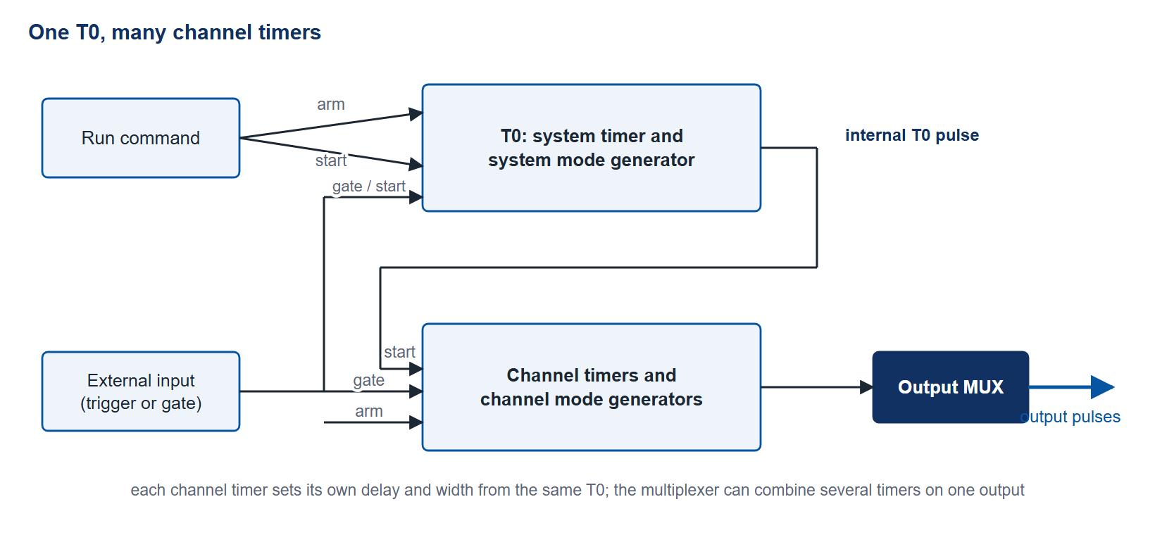
Every delay on a Berkeley Nucleonics generator is measured from a single reference moment called T0. Each channel then places its edge at a programmed delay after that instant (Figure 1). Understand where T0 comes from and you understand the whole timing system, because everything else is referenced to it. The question that defines a setup is what creates T0.
Internal triggering
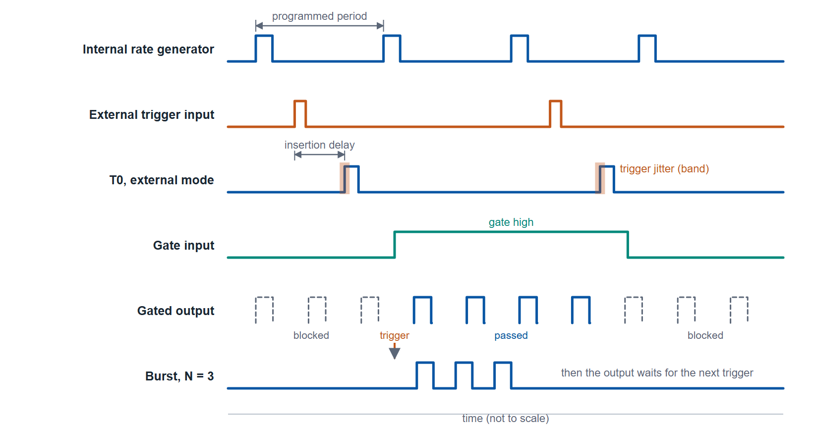
In internal mode the instrument's own rate generator produces T0 at a programmed repetition rate. This is the default for free-running experiments where the generator sets the pace. The Model 577 runs its internal rate from 0.001 Hz to 20 MHz; the Model 575 to 10 MHz; the Model 588B and the compact Model 525 to 20 MHz. The rate generator is locked to a low-jitter PLL, so the internal trigger is the lowest-jitter source available. If nothing external needs to drive the timing, internal mode gives the lowest jitter path to T0. Figure 2 shows the four ways T0 is produced or gated.
External triggering
In external mode an outside event creates T0. A photodiode watching a laser, a TTL pulse from another instrument, the sync from a power supply. The input comparator decides when the incoming edge crosses threshold, and that decision adds jitter. On the 575, 577 and 588B the trigger input accepts thresholds from 0.2 to 15 V, slope-selectable, with an insertion delay of 110 to 180 ns depending on the model and trigger jitter of 800 ps RMS. The 765 family accepts external triggers to 40 MHz; its published trigger jitter, under 30 ps RMS below 15 MHz, is measured from trigger in to trigger out. External triggering ties timing precision to the input stage, so a clean, fast-edged trigger matters.
Gated operation
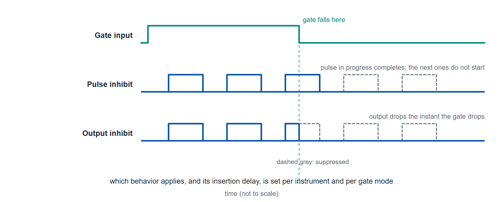
A gate does not create T0; it permits or blocks output while the generator runs. Raise the gate and pulses pass, lower it and they stop. Berkeley Nucleonics units distinguish pulse inhibit, which suppresses the pulse, from output inhibit, which holds the output line, with different insertion delays for each. Gating is how you window a continuous train to a region of interest, for example admitting laser pulses only while a sample is in position. Figure 3 contrasts the two behaviors. The 575, 577, and 588B all expose a global gate with per-channel control, so you can gate the whole instrument or selected channels.
Burst mode
Burst mode emits a fixed, counted number of pulses from a single trigger, then waits for the next. It bridges single-shot and continuous operation. A pump sequence that needs exactly 50 pulses per trigger gets 50, and then the output stops. The 577 counts bursts from 1 to 10,000,000 pulses, the 575 the same, the 525 from 1 to 1,000,000, and the 588B to 4,000,000,000 on its system timer. Duty-cycle mode is the sibling: a programmed count on, a programmed count off, repeated, useful for thermal management of a driven load.
Synchronizing multiple units
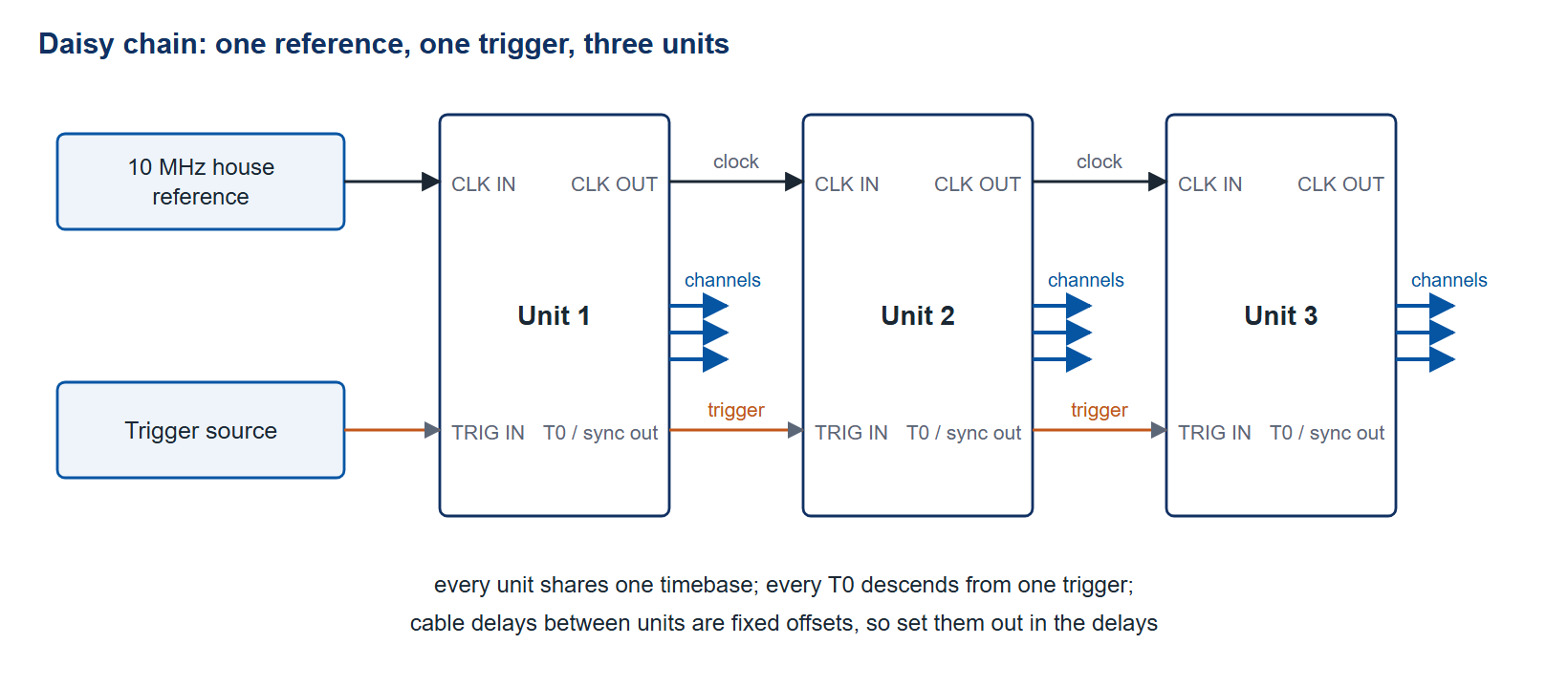
When one chassis runs out of channels, you tie several together. The standard method shares a common reference clock so every unit's timebase agrees, then distributes a common trigger so every unit's T0 fires together. The 575, 577 and 765 family accept a 10 to 100 MHz external clock and pass a clock out; the 588B accepts 10 to 80 MHz in discrete steps and outputs T0 or 10 to 100 MHz. Either way the clock out of one unit can feed the clock in of the next (Figure 4). The 588B carries Ethernet as standard and the 577 adds it with Option COM, for coordinating instruments across a rack or a room. For the tightest skew, lock every unit to the same physical 10 MHz source rather than running independent crystals.
The Model 725 and programmable trigger logic
The Model 725 takes a different approach to synchronization. Instead of one T0 fanning out to delayed channels, it provides eight inputs, eight outputs, and eight independent timers, with programmable boolean logic between them. Inputs can be combined with AND, OR, XOR, and negation before they start a timer, so an output can fire only when several conditions coincide. Throughput delay is about 11 ns with roughly 1 ns spread, and delay resolution is 10 ns. This is the tool for multi-trigger experiments: ballistics, explosive and airbag-squib testing, shock tubes, and two-pulse laser work where the trigger is a logical condition, not a single edge. Up to 64 complete settings can be stored for standalone operation.
Trigger I/O at a glance
| Model | Trigger modes | Max trigger rate | Trigger threshold | Trigger jitter |
|---|---|---|---|---|
| 525 | Internal, external, gate, burst, duty cycle | 20 MHz ext trig | 0.2–15 VDC, 30 V peak max, edge-selectable | <5 ns RMS (trigger input) |
| 575 | Internal, external, gate, burst, duty cycle | 5 MHz ext trig | 0.2–15 VDC | 800 ps RMS |
| 577 | Internal, external, gate, burst, duty cycle | 5 MHz ext trig | 0.2–15 VDC | <800 ps RMS |
| 588B | Single pulse, burst, duty cycle, external gate/trigger; dual trigger option | 5 MHz ext trig | 0.2–15 VDC, 30 V peak max | 800 ps RMS; insertion delay <160 ns |
| 725 | 8 inputs, programmable AND/OR/XOR/negate logic | 781 kHz repetition; 1 to 100 MHz external clock | logic-level inputs, 4.7 kΩ | 50 ps typ, 200 ps max (internal source); 10 ns max (asynchronous source) |
| 745T | External (pos/neg), internal, burst, prescaler, gate | <1 MHz repetitive | 0.1–5.0 V into 50 Ω | 25 ps + delay × 10⁻⁷ (external trigger) |
| 765 | Single, continuous, burst, gated | 40 MHz ext trig | ±8 V threshold, 50 Ω/1 kΩ | <30 ps trigger in to trigger out (≤15 MHz) |
| 765-HV | Single, continuous, burst, gated | 40 MHz ext trig | ±8 V threshold, 50 Ω/1 kΩ | <30 ps trigger in to trigger out (≤15 MHz) |
Table 1. Values from the current datasheets. Trigger jitter is RMS and, except where the row says otherwise, is measured from the trigger input to a channel output.
Choosing your trigger source
If the generator should set the pace, use internal triggering for the cleanest T0. If an external event owns the timing, accept the input-stage jitter and feed it the fastest edge you can. Use a gate to window a running train, burst to emit a counted set, and the 725 when your start condition is a logical combination of several signals. For more channels than one chassis holds, share a clock and a trigger across units.
Plan a synchronization scheme with us
Describe your triggers, the number of timed events, and how many channels you need, and we will lay out a single-unit or multi-unit scheme and check it against the datasheet figures. Reach Berkeley Nucleonics at info@berkeleynucleonics.com or 800-234-7858, or browse the full Pulse & Delay Generators documentation.