The Mission
Satellite links now reach well into Ka-band and beyond, and the ground equipment that talks to them has to be characterized across that whole span. SATCOM and ground-station test work covers uplink and downlink chains, frequency converters, and modem front ends. The common thread is the need for a clean, stable carrier that can stand in for a local oscillator or an uplink signal without adding noise of its own.
The Challenge
Phase noise sets a floor on the error-vector magnitude of a high-order-modulation link. A source whose phase noise is comparable to the device's masks the device's impairments and inflates error-vector magnitude on the bench. The source also has to reach the upper bands, since Ka-band and millimeter-wave converters cannot be tested with a generator that stops at 20 GHz. Coverage and spectral purity have to arrive together.
Recommended Berkeley Nucleonics Solutions
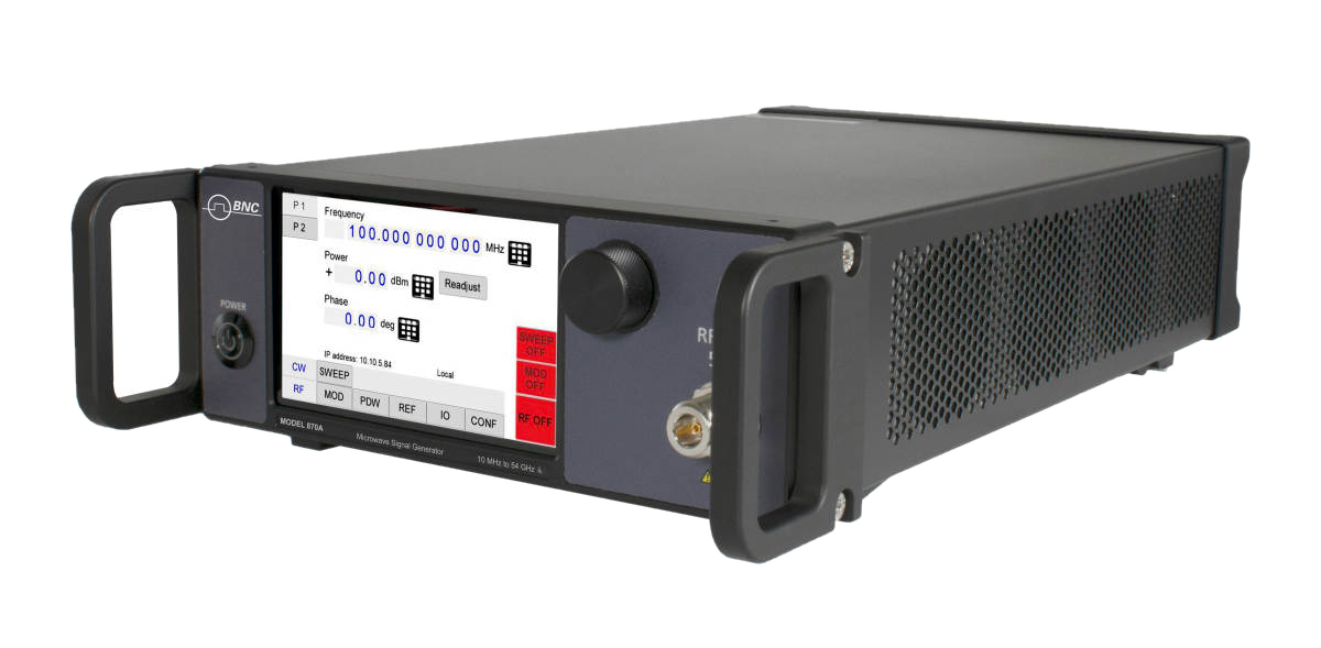
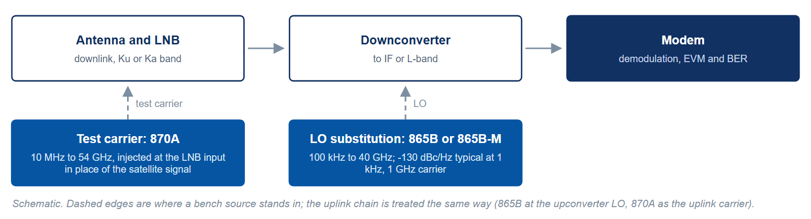
The Model 870A is the natural anchor here, covering 10 MHz to 54 GHz with low close-in phase noise (-100 dBc/Hz specified at 10 Hz offset, 1 GHz carrier, with Option LN or LN+) and single or multi-channel configurations. It reaches the full Ka-band span and above in one instrument.
The Model 871 extends phase-coherent coverage to 51 GHz with 5 µs switching (Option FS), a good fit when uplink and downlink need to stay locked together. For sources up to 40 GHz, the Model 865B is a compact, low-phase-noise bench generator (-130 dBc/Hz typical at 1 kHz, 1 GHz carrier) well suited to converter and LO substitution. Where lower-band uplink chains and IF sections dominate, the Model 845 covers 100 kHz to 26 GHz (settable to 30 GHz) with full modulation and a portable form factor with an external battery option for field ground-station work. Figure 1 sets the four against the satcom bands.
At 20 GHz the 870A is specified at -111 dBc/Hz at 1 kHz offset and -120 dBc/Hz at 20 kHz, delivers +20 dBm from 22 to 42 GHz and +15 dBm to 50 GHz, and holds level to 1.2 dB (0.4 dB typical) from 20 to 26 GHz between -15 and +15 dBm. LO substitution also needs a reference the station can trust: the 870A internal reference holds ±100 ppb from 0 to 50 °C, ±20 ppb with Option LN, and locks to the station's 10 MHz.
Why It Works
With source phase noise well below the device's, the measured impairments are dominated by the device under test. Reaching 54 GHz in a single box means one instrument spans IF through millimeter-wave instead of forcing a chain of converters into the test setup. And because several of these models share a coherent multi-channel design, a ground-station bench can drive uplink and downlink paths from one synchronized source.
Getting Started
Berkeley Nucleonics applications engineers help match the right source, channel count, and options to your test plan. Tell us your frequency span, switching budget, and channel needs, and we will recommend a configuration and arrange a demo.
Contact info@berkeleynucleonics.com or call 800-234-7858. Browse the full family on the RF & Microwave Signal Generators documentation page.