
The Mission
Antenna characterization and EMC testing both rest on a dependable swept or stepped carrier. Antenna ranges measure pattern, gain, and return loss across frequency, while EMC immunity and pre-compliance work injects controlled signals to see how a device responds. Neither task needs exotic modulation. What they need is a clean tone, accurate level, and a reliable sweep that the rest of the measurement chain can trust.
The Challenge
The source's harmonics and spurious outputs reach the receiver along with the test tone, so they can appear as artifacts in the pattern. EMC pre-compliance adds a different demand: broad frequency coverage and a controllable sweep so a device can be walked across the band. A compact, often flange-mounted or USB-powered source is welcome here, where the source has to mount near the antenna or inside the chamber.
Recommended Berkeley Nucleonics Solutions
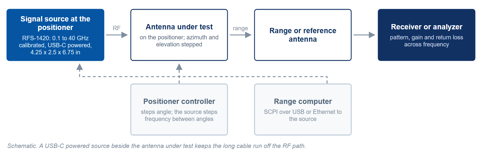
The RFS-1000 Series suits this work: a compact CW source in a 4.25 by 2.50 by 6.75 inch aluminum enclosure, powered over USB-C and stepped by SCPI over USB or Ethernet, calibrated to 40 GHz and settable to 42 GHz (RFS-1420), small enough to mount close to an antenna under test. For a full-featured bench source, the Model 845 covers 100 kHz to 26 GHz with CW and sweep plus full modulation when immunity testing calls for it.
Where sub-6 GHz coverage is enough, the Model 835 provides a 9 kHz to 6.1 GHz source with sweep that draws about 12 W. For an embeddable, phase-coherent flange-mount module to 40 GHz, the Model 866-M brings -70 dBc typical non-harmonic spurious from 1 to 20 GHz and passive cooling to fixed or chamber installations; its harmonics are -15 dBc typical from 1 to 4 GHz, so pattern work in that range needs a harmonic filter. Figure 1 sets the four on one frequency axis.
Level accuracy sets the amplitude floor of a pattern cut. The RFS-1420 is specified at ±1.0 dB from the low end to 20 GHz and ±2.0 dB from 20 to 40 GHz; the 845 holds 1.0 dB (0.3 dB typical) between -15 and +15 dBm; the 866-M holds 1.0 dB maximum below 15 GHz at 0 to 15 dBm. Harmonics on the RFS-1000 Series run under -25 dBc typical, so a cut taken near a harmonic of the test frequency needs a filter or a cleaner source: the 845-12 with Option FILT holds harmonics to -50 dBc or better from 8 to 12 GHz.
Why It Works
A clean, low-spurious source keeps the generator from writing its own artifacts into an antenna pattern, so the pattern contains no source harmonic or spur above the receiver's detection threshold. Wide, controllable sweep handles both pattern measurement across frequency and EMC immunity scans. And the compact module and USB-powered options in this family fit beside a positioner or inside a chamber, where a bench instrument needs rack or bench space, mounting near the antenna or inside a chamber without consuming a rack.
Getting Started
Berkeley Nucleonics applications engineers help match the right source, channel count, and options to your test plan. Tell us your frequency span, switching budget, and channel needs, and we will recommend a configuration and arrange a demo.
Contact info@berkeleynucleonics.com or call 800-234-7858. Browse the full family on the RF & Microwave Signal Generators documentation page.