Wireless & 5G/6G System Validation
Modern wireless systems pack more bits into less spectrum every generation. Wi-Fi 7, dense IoT deployments, LTE, and 5G NR all lean on high-order modulation, wide channels, and tight timing. That delivers throughput, but it also means the margin for error is thin. A few dB of distortion, a stray spur, a timing slip on a transient, and the link quality collapses. The system passes most of the time, then drops a frame for reasons that do not show up in a static measurement.
The errors that cost teams the most are the intermittent ones. A fault that fires once in ten thousand frames will not reveal itself on a single capture. By the time a swept analyzer finishes one pass, the event is long gone, and the operator is left staring at a clean trace that hides a real problem. Reproducing the fault on demand is often impossible. The instrument has to be watching at the moment it happens, with enough bandwidth to see the channel and enough memory to keep the evidence.
So validation needs three things at once: enough analysis bandwidth to cover a channel in one shot, demodulation that shows the constellation and the symbol errors behind it, and a way to capture a transient fault so it can be studied after the fact. A static spectrum is the smaller part of the job. The larger part is catching the system at the instant it misbehaves.
How the ICX-FieldHawk line solves it
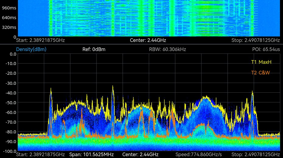
The ICX-FieldHawk receivers analyze in real time across wide channels, with up to 100 MHz of analysis bandwidth, so a 5G NR FR1 carrier of up to 100 MHz, an LTE carrier, or a Wi-Fi channel of up to 80 MHz fits in one capture rather than being stitched from sweeps. Wider channels (160 MHz Wi-Fi 6E, 320 MHz Wi-Fi 7, 400 MHz NR FR2) are measured in sections. The real-time density display accumulates tens of thousands of spectra per second, so a slow drift or a sudden degradation is visible as it develops rather than after.
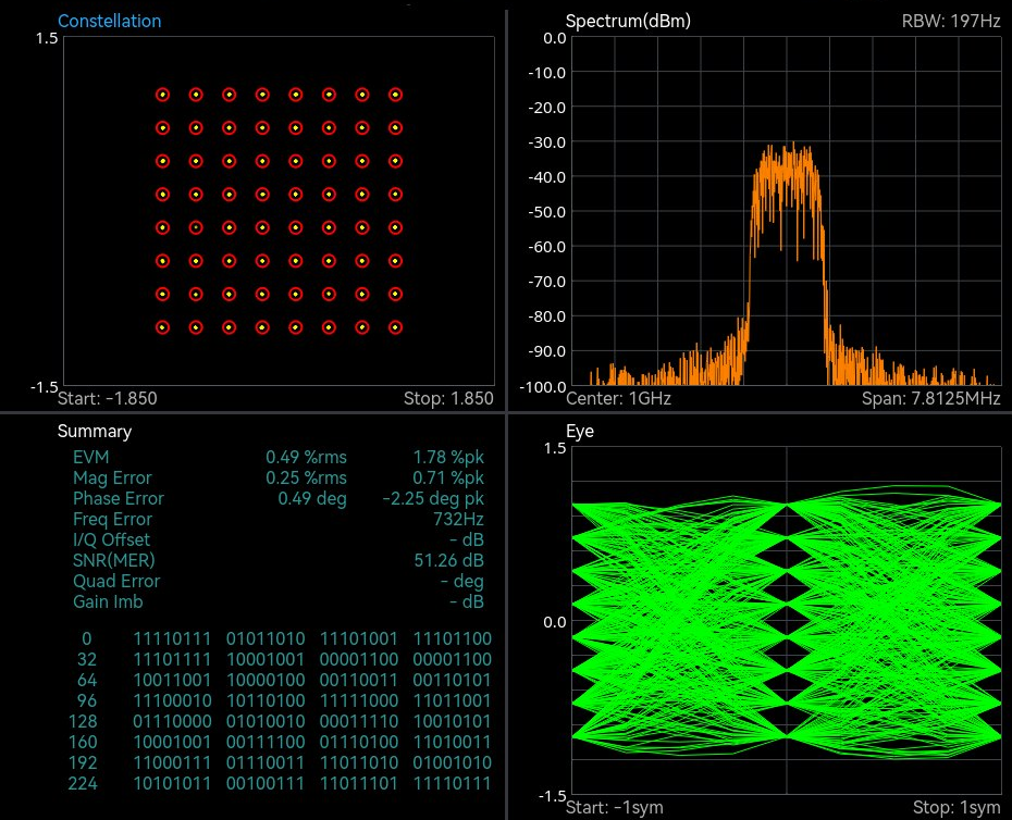
Digital Demodulation (option 71) in SpectraCore covers 2ASK, 2FSK, 4FSK, GMSK, BPSK, QPSK, 8PSK and 16, 64, 128 and 256 QAM. An operator pulls a constellation and inspects the symbol errors that point at the root cause, whether that is amplifier compression, phase noise, or a timing fault. Power Detection mode adds the time dimension: power versus time across the analysis bandwidth at 8 ns resolution, with PosPeak, NegPeak, Sample, Average, RMS and MaxPower detectors, which is the view that shows a transient fault.
The decisive feature for intermittent bugs is record and playback. The ICX-FieldHawk line captures the raw IQ of an event, at up to 100 MHz bandwidth into 128 Mbyte of built-in memory or continuously at up to 25 MHz, so a fault that lasted a fraction of a second in the lab can be replayed, demodulated, and dissected as many times as it takes. Capture the failure once and the analysis can be repeated as often as needed.
Which models and accessories fit
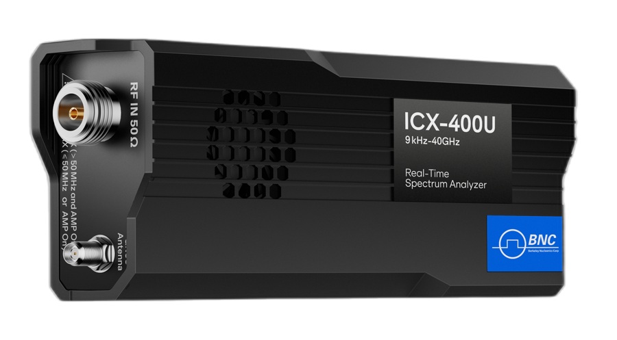
For lab and integration work, the ICX-Series USB core module is the natural fit. It drops into a workstation, an automated test setup, or an SDR-based development platform, exposing the full real-time engine and 100 MHz of analysis bandwidth through a programmable interface. The ICX-400U reaches 40 GHz, which covers FR1 and the FR2 bands n257, n258, n260 and n261 (n259 extends to 43.5 GHz); the ICX-200U covers to 20 GHz. 6G candidate bands above 40 GHz need a different receiver.
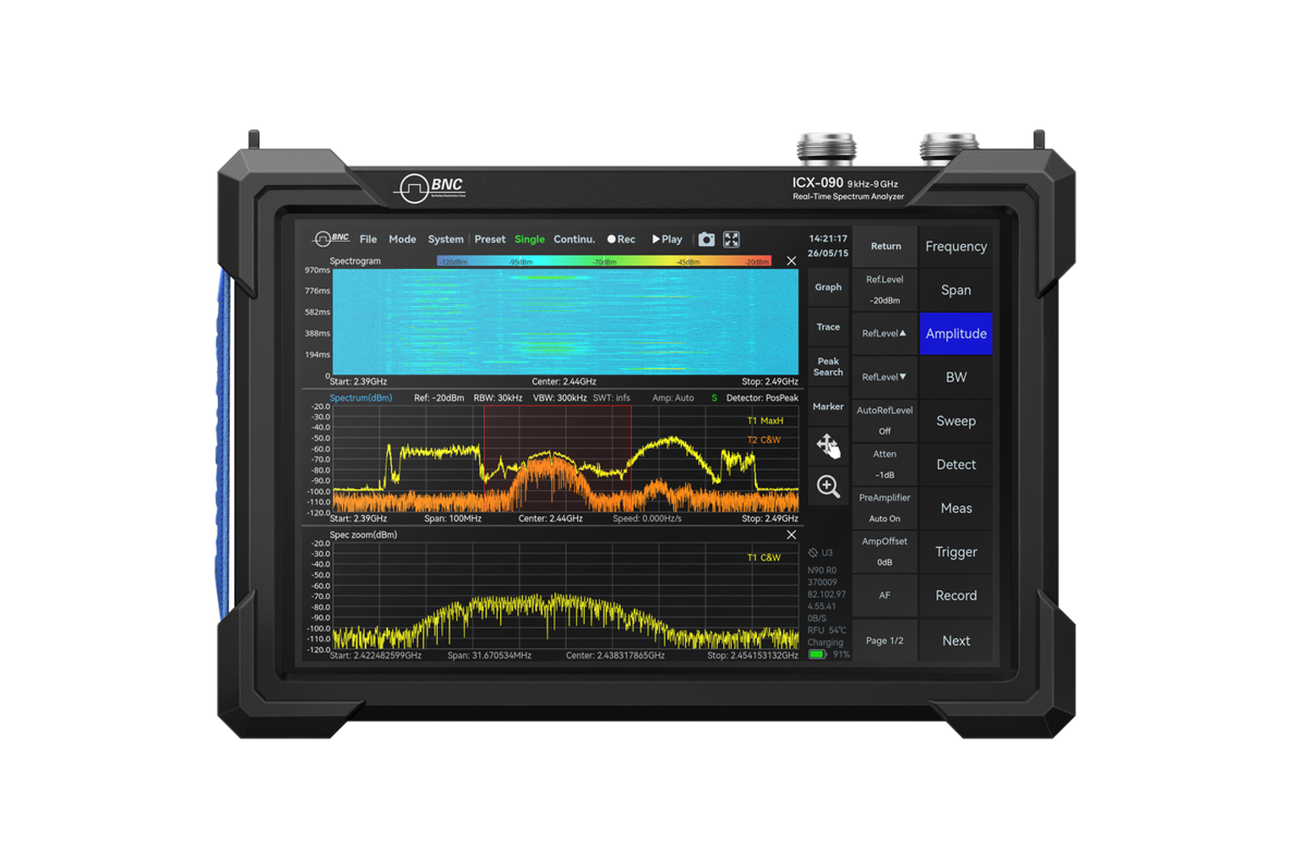
For bring-up at the antenna, on the production floor, or out at a live cell site, the ICX-FieldHawk handheld puts the same real-time analysis where the system runs. Engineers can verify a deployment, chase an over-the-air anomaly, or confirm a fix in the field without hauling a bench unit, then bring the captured IQ back for deeper analysis.
Where over-the-air work calls for directional reception, pair either unit with the RFA-3100-N antenna to isolate a signal of interest from a crowded band.
| Need | Recommended model | Why |
|---|---|---|
| Lab / ATE / SDR integration | ICX-Series (ICX-200U, ICX-400U) | USB or LAN module, 100 MHz analysis bandwidth, to 20 or 40 GHz |
| Bench, line, and field bring-up | ICX-FieldHawk handheld | Same real-time engine where the system operates |
| Directional over-the-air work | RFA-3100-N | Isolate a signal of interest in a crowded band |
Recommended configuration
A capable validation kit centers on the ICX-Series with 100 MHz analysis bandwidth and coverage to 40 GHz for lab, ATE, and mmWave work, paired with an ICX-FieldHawk handheld for bench and field bring-up. Both run SpectraCore with Digital Demodulation (option 71), Power Detection, and IQ record and playback. Add an RFA-3100-N for directional over-the-air capture. That setup covers wide-channel analysis, symbol-level debugging, and the transient-fault capture that intermittent errors demand.
Wi-Fi 7, 5G NR, and 6G research each have different channel and band needs. A Berkeley Nucleonics applications engineer can match the configuration. Reach us at info@berkeleynucleonics.com or 800-234-7858.
For a quick question, chat with an engineer at berkeleynucleonics.com.