1Introduction

Optics, photonics and laser applications include automotive LiDAR, medical instruments, aerospace and defense systems, quantum experiments and laser sensors. Each needs electrical signals with a defined amplitude, edge rate and timing: modulator drive, pulse sequences, and laser triggers.
An arbitrary waveform generator produces most of these signals from one instrument. This note covers the integrated-optical modulator and its drive requirement, the Model 685 output specifications that bear on that requirement, measured pulse captures, an example from quantum optics, and the role of the 685 in pulsed laser diode systems.
Different applications call for different signals. A few representative examples show the range the Model 685 covers:
- Electro-optic modulators. Pulses and patterns up to 5 Vpp into 50 Ω, which drive a modulator with a half-wave voltage up to 5 V without an external amplifier.
- Quantum optics. Generation of varied signals and pulse sequences that serve as stimuli for quantum-optics experiments.
- Pulsed laser diodes. Trigger and shaped drive signals for a pulsed laser diode driver, and modulator drive for an externally modulated source.
2Integrated-Optical Waveguides
Integrated-optical waveguides guide light along a defined path in a way that is analogous to optical fiber. The waveguide is a channel with a higher refractive index than the material around it.
Light is held inside the channel by total internal reflection at its walls. Depending on the wavelength, the substrate refractive index, the index difference, and the width and depth of the channel, one or more transverse oscillation modes can be excited. Single-mode operation is of particular interest because it is essential to the function of many integrated-optical elements. In optical communication technology especially, these elements are usually supplied with optical fibers already attached.
The linear electro-optic effect, also called the Pockels effect, is a second-order nonlinear effect. It is the change in the refractive index of an optical material when an external electric field is applied. The index change is proportional to the field strength and depends on the field direction relative to the crystal axes and on the polarization of the light. The preferred material for integrated-optical modulators is lithium niobate (LiNbO3). When a field is applied to a waveguide through electrodes of length L, the refractive index changes in the region between the electrodes, which produces a phase shift in the guided light. That phase shift is linear in the applied voltage (Figure 1).
3Phase and Amplitude Modulation
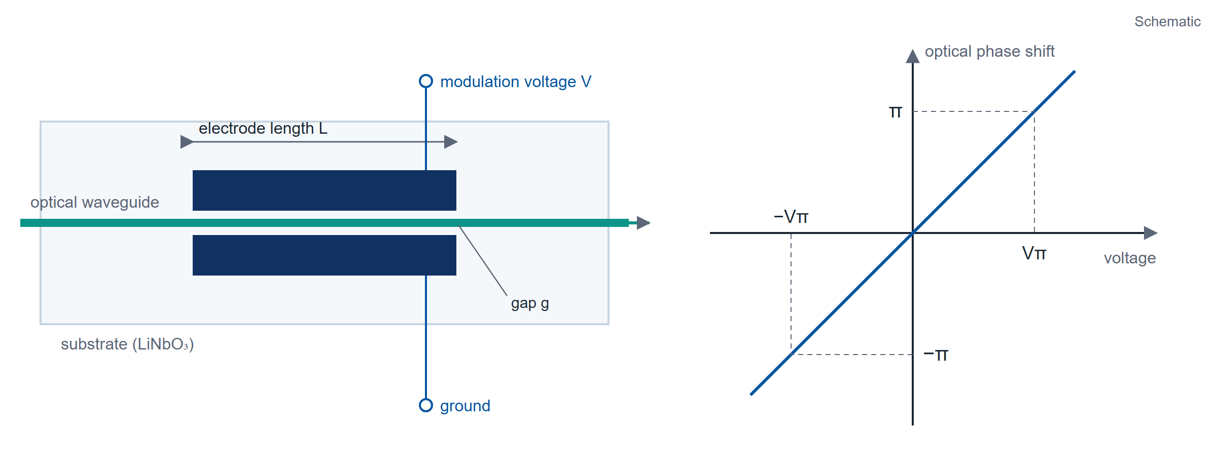
The voltage required is typically a few volts. Longer wavelengths need a higher voltage than shorter ones for a given electrode geometry: for example, about 3 V in the red at 635 nm and about 10 V in the telecommunication range near 1550 nm. Because the electro-optic response is fast, the control voltages are low and the electrode geometry can be optimized, modulation at gigahertz frequencies is achievable. A phase modulator placed in an integrated Mach-Zehnder interferometer forms an amplitude modulator (Figure 2).
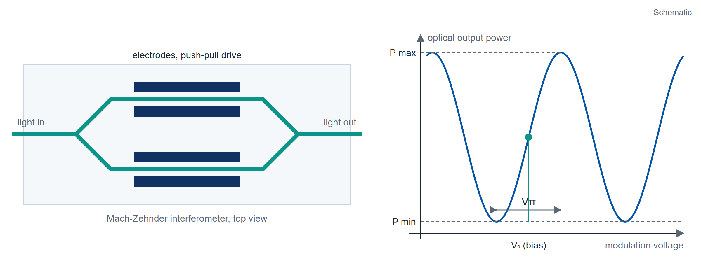
Applying a voltage creates a relative phase difference between the two branches, and interference then changes the output power at the device output. The transmission can be controlled between a minimum and a maximum value, from P min to P max. A relative phase difference of pi is needed to switch from the on state to the off state or back. The voltage that produces this is called the half-wave voltage, V pi, of the amplitude modulator. Because of push-pull operation, the half-wave voltage of an amplitude modulator is half that of a phase modulator with the same electrode length. For the example geometry above, that is about 1.5 V in the red at 635 nm and about 5 V in the telecommunication range near 1550 nm.
When an RF signal is applied to the electrodes as the modulation voltage, that electrical input is translated into amplitude information. The optical output depends on the magnitude and shape of the voltage, and therefore on where the modulator is biased on its characteristic curve. A binary electrical input maps to a binary optical output (Figure 2). If the drive amplitude departs from Vπ or the bias departs from the intended point, the modulator produces incorrect optical levels in binary operation, or harmonics in analog operation.
4Driving Modulators with the Model 685
The Model 685 generates the modulation voltage directly. Its single-ended output delivers up to 5 Vpp into 50 Ω with a ±2.5 V offset range. In AFG mode the minimum specified pulse width is 500 ps, and square and pulse edges are 300 ps (20% to 80%) and 400 ps (10% to 90%). In True Arb mode the instrument plays each sample at up to 6.16 GS/s, and rise and fall time is ≤ 110 ps (20% to 80%) and ≤ 175 ps (10% to 90%) at 1 Vpp single-ended, which gives a calculated bandwidth of ≥ 2 GHz (0.35 / 175 ps). A modulator with a half-wave voltage up to 5 V, such as the 1550 nm amplitude modulator example above, is driven across its full transfer range without an external amplifier; a modulator with a higher Vπ needs one.
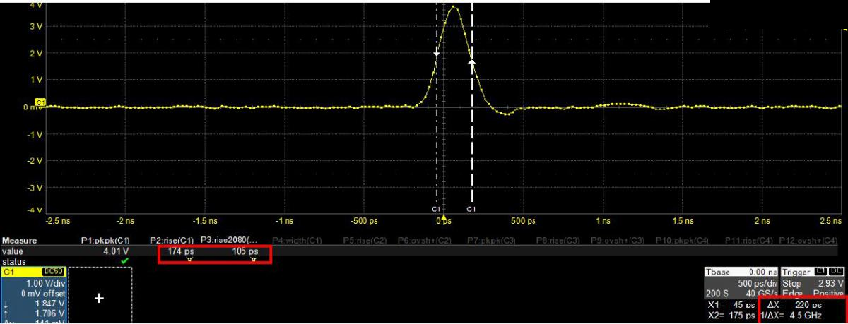
A True Arb waveform can be narrower than the 500 ps AFG minimum, but widths below 500 ps are not specified, and below 500 ps the pulse amplitude falls below the set value. Figure 3 shows one such pulse: the measurement reads 4.01 V peak to peak, and the cursors near the half-amplitude points are 220 ps apart.
The True Arb sequencer builds pulse shapes sample by sample, which gives finer control over the optical output. Figure 4 shows a pulse train at 5.22 V peak to peak with a 974 ps pulse; its 20.78 ns period is a 128-sample waveform played at 6.16 GS/s (128 / 6.16 GS/s = 20.78 ns). Figure 5 shows a modulator drive pattern of two short pulses and one 48.7 ns pulse at 3.49 V peak to peak, with 110 ps rise from 20% to 80%.


5Quantum Optics
Color centers in diamond are defects in the crystal lattice, where carbon atoms are replaced by other kinds of atoms and adjacent lattice sites are left empty. Because of their bright single-photon emission and optically accessible spins, color centers are candidate solid-state quantum emitters for quantum information processing and quantum networks (Figure 6). Two of the most mature systems for entangling spin qubits with coherent photons are quantum dots and the nitrogen-vacancy (NV) center in diamond. NV centers show coherence times exceeding 1 s, but they lack efficient emission into the zero-phonon line (ZPL) needed to yield indistinguishable photons. Quantum dots show strong emission properties but are limited to coherence times of tens of nanoseconds. The challenge with solid-state quantum emitters is to obtain good single-photon generation and long spin coherence in the same system.
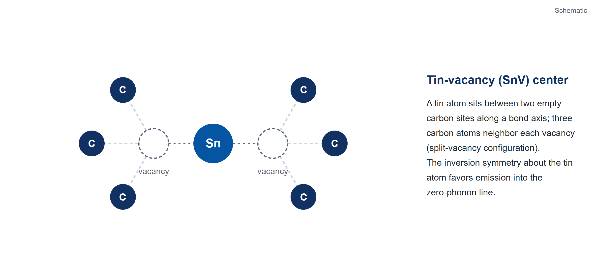
Recent work on the group IV vacancy centers in diamond, which include the silicon-vacancy (SiV) and tin-vacancy (SnV) centers, shows progress toward both goals. Their crystallographic symmetry favors emission into the ZPL, which gives them strong optical properties. SiV centers show 10 ms coherence times at 100 mK. The heavier tin-vacancy center is predicted to reach similar times at 2 K, a temperature standard helium cryostats reach, and its strong, stable ZPL emission in nanostructures suits it to nanophotonic platforms.
The Model 685 Series has been used to control the pulse sequences that manipulate single tin-vacancy centers in diamond. The instrument generates narrow electrical pulses with an amplitude greater than 1.5 V to drive an electro-optic amplitude modulator, which cuts short laser pulses from a continuous beam; optical pulses close to Gaussian in shape, with a full width at half maximum as narrow as 280 ps, were produced this way. Figure 7 shows an electrical Gaussian pulse of this kind. The Model 685 has also driven an electro-optic phase modulator to generate frequency sidebands up to about 2 GHz, which addresses two optical transitions with phase-stable laser fields.

The digital output channels of the Model 685 can control acousto-optic amplitude modulators or generate trigger pulses for the timing of experimental sequences. Where the next step of a protocol depends on a readout earlier in the sequence, the 685 sequencer supports loops, jumps and conditional branches across up to 16,384 entries.
6Pulsed Laser Diode Driving
Pulsed laser diodes deliver short pulses of high optical power, and are used in military target designation and rangefinding. Improvements in technology and reductions in cost have opened uses in metrology and medicine.
Continuous versus pulsed operation
Standard laser diodes are built to emit continuous-wave radiation, with power from a few milliwatts to a few watts. A pulsed laser runs at a lower duty cycle, so heat removal is less of a concern. A pulsed laser's output facet also generally has much lower reflectivity than a CW device. On typical CW lasers, threshold is kept low by limiting the emitting width to 5 to 35 microns. Threshold current is directly proportional to that width, but the high gain in pulsed lasers allows the width to grow up to 400 microns, with a matching increase in peak power.
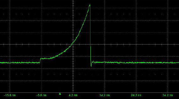
Pulsed laser diodes are designed to be driven with high-current pulses that produce short, high-power optical pulses. To reach high peak power, the duty cycle is typically kept below 0.1 percent: a 100 ns optical pulse at 0.1 percent duty repeats every 100 microseconds, a 10 kHz repetition rate. Maximum pulse lengths are typically around 200 ns, with 3 to 50 ns pulses being more common. Creating these optical pulses takes currents on the order of several tens of amperes, which requires fast switching transistors and careful circuitry, with every electrical connection kept as short as possible to reduce inductive losses.
The first commercial GaAs pulsed lasers emitted at 905 nm. That wavelength sits close to the peak responsivity of silicon detectors and near a water absorption peak, which reduces ambient light and increases detection sensitivity. As new semiconductor materials arrived, a wider range of wavelengths became feasible. Lasers in the 1550 nm range have drawn more attention for their better transmission through fog and smoke, and because that wavelength is less hazardous to vision than shorter ones.
Time of flight and other functions
Many pulsed-laser-diode applications are variants of the original rangefinding application, in which target distance is found by measuring the flight time of a laser pulse reflected or backscattered from the target. With this principle, long-range instruments measure distances up to 10 km. Laser speed guns, unlike RF speed guns that read velocity from the Doppler shift, calculate velocity from distance measurements taken at different times. Eye-safe rangefinders are also built for recreational uses, from hunting to golf (Figure 8 shows the collision-detection case).
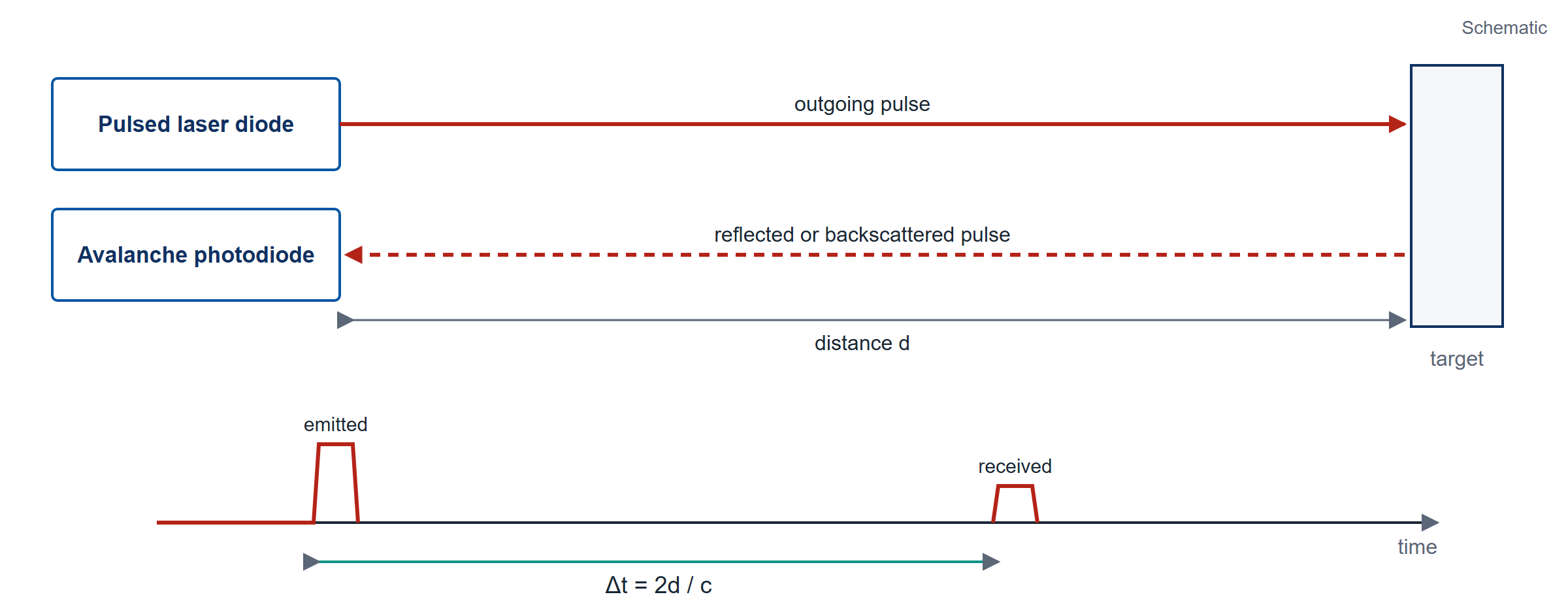
Pulsed laser diodes supply the optical signal in automotive collision-avoidance systems, serve as navigational aids for ships in ports and harbors, appear in ceilometers for cloud-base measurement at airports, and support surveying and construction. In a laser safety scanner, pulsed laser diodes form a curtain of light around hazardous areas such as automated production lines, and coded pulse emission lets a two-dimensional curtain distinguish allowed from disallowed shapes. The high peak power from pulsed laser diodes, paired with avalanche photodiodes, gives the sensitivity needed to tell shapes apart.
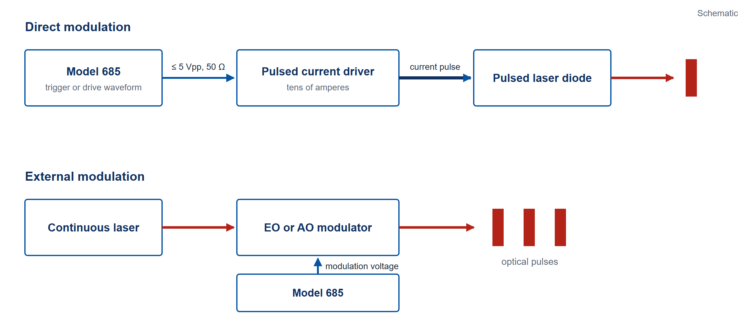
Short, high-power pulses from laser diodes serve applications that continuous-wave diodes cannot address, for technical or economic reasons. A diode that needs tens of amperes is driven by a pulsed current driver. The Model 685 output is a 50 Ω source with a ±2.5 V window into 50 Ω (an open-circuit swing of ±5 V), so the current it delivers into a low-impedance load is below 100 mA. It drives low-current diodes and modulators directly, and for high-current diodes it supplies the trigger or the shaped drive waveform to the driver. Alternatively the laser runs continuously and an electro-optic or acousto-optic modulator, driven by the 685, forms the optical pulse. Figure 9 shows the direct-modulation arrangement.
The drive waveform for a pulsed driver or a modulator can be rectangular, Gaussian or exponential. In True Arb mode the Model 685 plays any of these shapes at up to 5 Vpp into 50 Ω, with rise and fall time ≤ 110 ps (20% to 80%) at 1 Vpp single-ended; in AFG mode the minimum specified pulse width is 500 ps. Figure 10 shows rectangular pulses captured on an oscilloscope.

7Conclusion
The Model 685 Series covers modulator drive up to 5 Vpp into 50 Ω, shaped pulses with edges of 110 ps or less (20% to 80%, 1 Vpp), sequenced pulse patterns for quantum-optics experiments, and the trigger and shaped drive signals for pulsed laser diode drivers. Each of these uses rests on the conditions stated above: output amplitude into 50 Ω, edge time at 1 Vpp, and the 500 ps minimum pulse width in AFG mode.
Talk to an application engineer
Berkeley Nucleonics can help you match a Model 685 Series configuration to your optics, photonics, or laser setup. Call 800-234-7858 or email info@berkeleynucleonics.com.
For a quick question, chat with an engineer at berkeleynucleonics.com.
Ask now → Chat with our assistant and get an answer in seconds.