
Time-of-Flight Mass Spectrometry
Time-of-flight mass spectrometry resolves species by the time it takes an ion to travel a known flight path. Lighter ions arrive first, and flight time grows as the square root of m/z (Figure 1), so the measurement rests on one moment: the instant the extraction grid pulses and launches a packet of ions down the drift tube. Mass resolution, peak shape, and the ability to separate two species that differ by a fraction of a dalton all trace back to how cleanly that launch happens.
The same logic governs the deflection plates that steer and gate the beam, the Bradbury-Nielsen and beam-blanking gates that select which ions pass, and the pulsed optics in injectors and accelerator front ends. In each case a high-voltage transition has to start at a precise, repeatable moment, rise quickly to a flat level, and hold that level until the packet has cleared the region. The extraction pulse is the time zero for every flight-time measurement the instrument makes.
The Challenge
An extraction grid or deflection plate is a capacitive load, not a matched 50 ohm line: plate plus wiring is often tens to hundreds of picofarads. Current flows only while the voltage changes, I = C·dV/dt, so a fast edge into a real plate takes a brief, large current from the output stage. Moving 100 pF through 3,000 V in 25 ns takes 12 A. An output stage that cannot source that current slows the edge; current driven into lead inductance without damping produces ringing.
Ringing and overshoot degrade TOF resolution directly. A flat top that moves after the transition imprints that movement on the launched ion energy, which spreads arrival times and widens peaks. Jitter does the same in the time domain: if the launch moment shifts from shot to shot, every accumulated spectrum is the sum of slightly misaligned events. The requirement is a high-voltage pulse that is fast, flat, clean and repeatable into a capacitive load.
There is also the matter of bipolar geometry. Real ion optics frequently need to sit at one potential and then swing to another, sometimes crossing zero, so the useful instrument is one that defines an upper and a lower voltage and snaps cleanly between them on command.
The BNC Approach
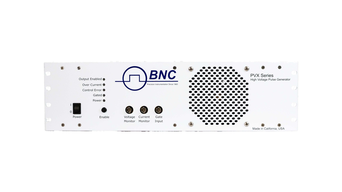
The DEI PVX pulse generators are designed for capacitive loads. The output stage is a half-bridge (totem-pole) design that drives the load actively in both directions, sourcing current to charge the plate on the rising edge and sinking it on the falling edge. That two-sided drive keeps both edges fast and the flat top settled when the load is a grid or a pair of plates rather than a matched cable.
On the PVX-4141 and PVX-4110 the output switches between two user-supplied DC supplies, VHigh and VLow, so it rests at one potential and switches to the other for the width of the gate. That maps onto how extraction and deflection optics are biased: one instrument holds a standing potential and pulses a packet without external level-shifting. Front-panel voltage and current monitors bring the output waveform to an oscilloscope (1000:1 and 10 A/V on the PVX-4141; 2000:1 and 10 A/V on the PVX-4110), so the engineer can see the edge into the real load, check the flat top, and watch for ringing as the load or rate changes.
The PVX-4141 runs from single shot to 30 kHz continuous at 3,500 V, and to 400 kHz continuous at lower load capacitance or voltage; the PVX-4110 runs from single shot to 10 kHz at 10,000 V. Rise and fall are 25 ns or less on the PVX-4141 (50 pF load, 6 ft of RG-59) and under 60 ns on the PVX-4110 (50 pF load, 4 ft of RG-11), with shot-to-shot jitter under 200 ps and under 1 ns respectively.
Recommended Instruments
For TOF-MS extraction and deflection, the default choice is the PVX-4141. It delivers up to 3,500 V with rise and fall of 25 ns or less into a 50 pF load, jitter under 200 ps shot to shot, a 60 ns minimum pulse width, and operation from single shot to 30 kHz continuous at full voltage. Throughput delay is 120 ns typical, a fixed offset that the timing system of the instrument can absorb.
For larger extraction stacks, longer flight regions, or accelerator front-end optics that need more voltage, the PVX-4110 extends the same design to ±10,000 V, with rise and fall under 60 ns, jitter under 1 ns, and single shot to 10 kHz. For moderate voltage from built-in supplies, the PVX-4000-2kV produces bipolar pulses within a shared 2,000 V budget (V+ plus |V−| up to 2,000 V), with levels set from the front panel, RS-232 or USB and rise and fall of 50 ns or less from 500 V to 2,000 V. Its external gate runs from single shot to 100 kHz, and the PVX-4000-2kV-EX, which takes external supplies instead, extends that to 600 kHz. The PVX-4141 and PVX-4110 share the VHigh/VLow supply inputs and the voltage and current monitors; the PVX-4000 carries a voltage monitor and a sync output and no current monitor.
Before specifying a model, estimate the plate-plus-wiring capacitance and the rise time you need. The peak current the pulser must source scales with both, so a faster edge into a larger plate moves the requirement up the line. An applications engineer can run that budget with you.
Getting Started
Start by characterizing the load: the electrode capacitance, the voltage swing your ion optics require, the polarity arrangement, and the repetition rate of your acquisition. Decide whether you need a standing bias with a pulsed transition, which the VHigh/VLow inputs of the PVX-4141 and PVX-4110 serve directly, or a gate to and from ground. The voltage and rate then select the model, and the built-in monitors show the edge into your grid from the first day of operation.
Talk to a BNC applications engineer at info@berkeleynucleonics.com or 800-234-7858. Bring your electrode capacitance, required voltage swing, and acquisition rate, and we will match a DEI pulse generator to the launch precision your spectrometer needs.