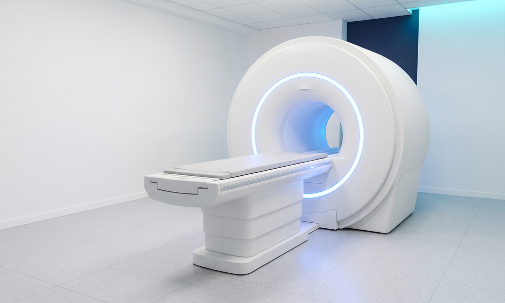
MRI & Medical Imaging
Magnetic resonance imaging turns a carefully orchestrated sequence of magnetic and radio-frequency events into a picture of the body. Inside the bore, gradient coils shape the spatial encoding while an RF chain excites and refocuses the spins, and image quality depends on how faithfully each of those signals is produced. Research and development labs pushing MRI forward, toward stronger high-field systems for clearer brain imaging and toward low-field systems that bring imaging to places that have none, build and validate these signal chains on the bench long before a system reaches a patient.
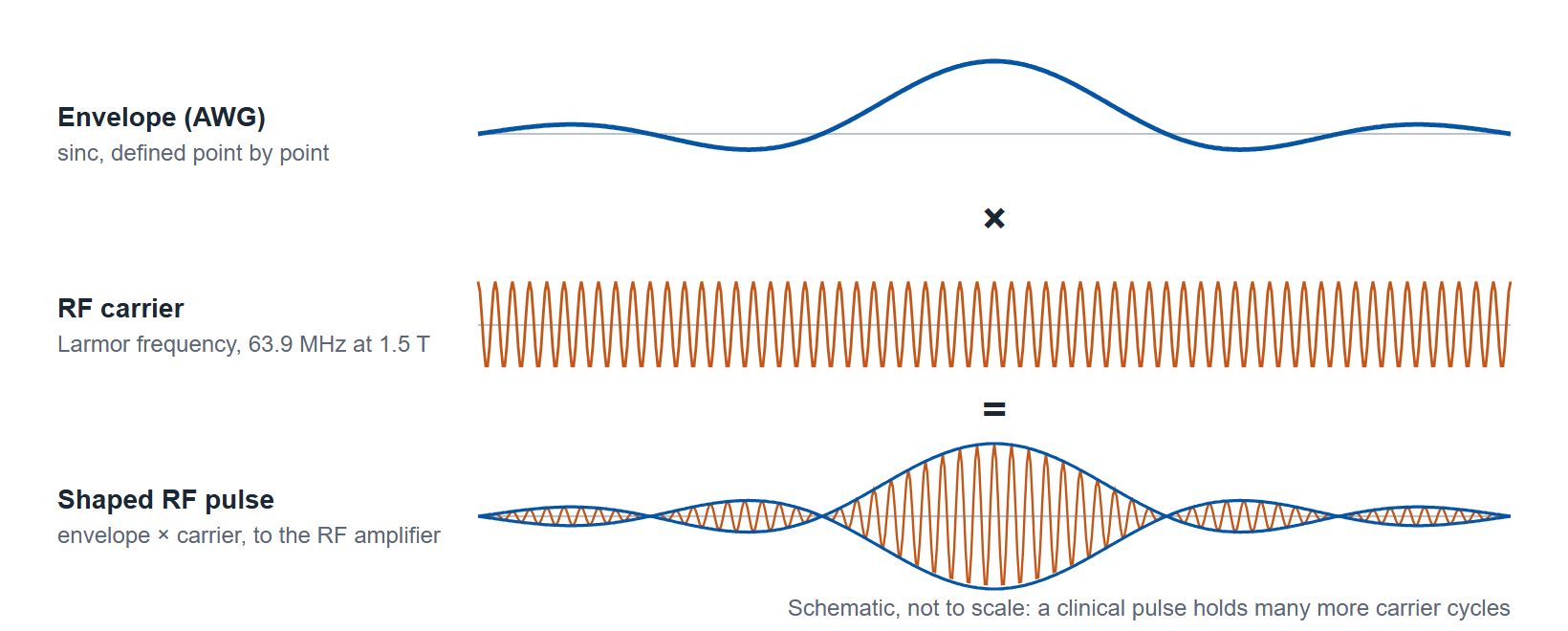
An MRI system relies on two kinds of signal working together: an RF carrier at the Larmor frequency, 42.58 MHz per tesla (63.9 MHz at 1.5 T, 127.7 MHz at 3 T), that excites the spins, and arbitrary waveforms that shape the RF envelope and drive the gradient coils. Figure 1 shows the RF side, a sinc envelope modulating the carrier. Because MRI is performed on people, the bench also confirms that delivered RF power stays within safe limits, which is why these labs pair waveform generation with calibrated RF power sensing.
Why an arbitrary waveform generator fits
MRI sequences are not single tones. A gradient waveform may ramp, hold, and reverse on a defined schedule, and an RF excitation may need a precisely shaped envelope such as a sinc or an adiabatic profile to rotate the spins the way the sequence intends. These are arbitrary shapes, defined point by point, and an arbitrary waveform generator exists to play exactly that: a user-defined sample stream rather than a fixed library function. That makes it the natural source for both the gradient drive and the RF modulation envelope, and the natural tool for emulating the signals a receive chain expects to see during development and test.
The demands are specific. Gradient and RF events have to land in a fixed relationship across the whole sequence, so timing has to be tight and repeatable from shot to shot. The envelopes have to be smooth and faithful, because a distorted RF pulse rotates the spins imperfectly and a noisy gradient blurs the encoding, both of which show up in the image. And the sequences are long, so the generator has to hold the full pattern rather than loop a short fragment. These requirements apply together, on the same channels: clean amplitude, fine timing, multi-channel coordination and deep memory.
The capabilities that matter
Multi-channel synchronized waveforms. A sequence drives more than one line at once. Gradient channels, the RF envelope, and the trigger and gating signals all have to move together against a shared reference rather than drifting apart over a long acquisition. A generator that synchronizes its channels, and synchronizes multiple units when a setup outgrows one chassis, keeps the whole sequence aligned to a single definition of time.
Precise, low-jitter timing. The boundary between excitation, encoding, and readout is defined in time. Low trigger jitter and fine timing resolution let each event land where the sequence expects it, shot after shot, so the encoding stays consistent and the emulated returns stay coherent.
Arbitrary pulse shaping with clean amplitude. The point of an arbitrary waveform generator is the shape. High vertical resolution keeps amplitude steps small and the envelope faithful through the gradient amplifier or the RF modulator, so the spins see the profile the sequence designed rather than a quantized approximation of it.
Deep waveform memory. Imaging sequences are long and rarely repeat a short pattern. Deep memory lets the generator hold a full multi-step sequence and play it through without looping, which matters for faithful sequence reproduction and for emulating a realistic stream of returns.
Which models fit

For gradient and RF envelope work where amplitude fidelity is the priority, start with the 16-bit Model 675 or Model 685 (Figure 3). Sixteen bits give 65,536 levels across the output range, which keeps the envelope finely graded through the modulator or gradient amplifier. The Model 675 is the gradient-drive candidate: 6 Vpp into 50 Ω, or 12 Vpp with the HV option, and the amplitude doubles into a high-impedance input, to 24 Vpp (±12 V) with the HV option. Where a gradient amplifier specifies a ±10 V analog input, the 675 with the HV option covers it directly. Its 1.2 GS/s sample rate and 400 MHz sine range also cover the RF carrier at 1.5 T and 3 T. The Model 685 adds sample rate, 6.16 GS/s (12.32 GS/s in RF mode, with carriers to 6 GHz), for envelope and emulation work above that.
Where the work calls for the highest sample rate, the faster edges of short pulses or the emulation of higher-bandwidth returns, the Model 686 fits: 20 GS/s at 14 bits. The three models use different synchronization arrangements: a QSFP sync bus on the 686, an Infiniband 4X sync bus on the 685, and no multi-unit bus on the 675. A mixed bench therefore shares one timebase through a common external reference clock, for example 10 MHz, which is inside every model's reference input range (5 MHz to 100 MHz on the 675, 5 MHz to 200 MHz on the 685, 5 MHz to 500 MHz on the 686). Trigger the units from one source and measure the residual offset between them once at setup. Table 1 lists the datasheet figures for the three models.
| Datasheet figure | Model 675 | Model 685 | Model 686 |
|---|---|---|---|
| Vertical resolution | 16 bit | 16 bit | 14 bit |
| Sample rate, True Arb | 1 S/s to 1.2 GS/s | 1 S/s to 6.16 GS/s (12.32 GS/s in RF mode) | 1 S/s to 20 GS/s |
| Analog channels | 2, 4 or 8 | 2, 4 or 8 | 2 or 4 |
| Amplitude into 50 Ω, single-ended | 6 Vpp; 12 Vpp with HV option; doubles into high impedance | 5 Vpp | 5 Vpp |
| Waveform memory per channel | Up to 1,024 Msamples | 2 Gsamples (4 Gsamples optional) | 9.6 Gsamples on CH1 and CH3; 1.17 Msamples (CH2, 2-channel) or 589 ksamples (CH2 and CH4, 4-channel) |
| Rise / fall, True Arb, 1 Vpp single-ended, 10% to 90% | ≤ 1.1 ns | ≤ 175 ps | ≤ 70 ps |
| Sine, AFG mode | To 400 MHz | To 2 GHz | To 6.5 GHz |
| Multi-unit synchronization | No multi-unit bus | Up to 4 units, Infiniband 4X | Up to 4 units, QSFP |
| Reference clock input | 5 MHz to 100 MHz | 5 MHz to 200 MHz | 5 MHz to 500 MHz |
Talk to an application engineer
Berkeley Nucleonics can help you match a Model 685, Model 675, or Model 686 configuration to your MRI gradient, RF pulse, and signal-emulation bench. Call 800-234-7858 or email info@berkeleynucleonics.com.
For a quick question, chat with an engineer at berkeleynucleonics.com.
Ask now → Chat with our assistant and get an answer in seconds.