Serial Pattern Generation (SPG)
Serial pattern generation is the act of producing a defined sequence of bits, symbol by symbol, on one or more output channels so that a digital device, a serial link, or a logic block can be driven, stressed, and characterized. A serial pattern can be a fixed word, a long pseudo-random bit sequence (PRBS), a hand-built custom stream, or a deliberate stress pattern designed to push a receiver toward its limits. In every case the value of the pattern depends on more than the bits alone. It depends on how cleanly each edge is shaped, where each voltage level sits, and how precisely the channels line up against one another. That is the gap between a logic-only pattern source and a serial pattern generator built on an arbitrary waveform engine.
The serial pattern mode on the Berkeley Nucleonics arbitrary waveform generators combines the bit-level control of a data pattern generator with the analog control of an arbitrary waveform generator, so the pattern and the signal that carries it are programmed in one instrument. Each symbol sits on the instrument timebase, each transition between levels has a programmed shape and duration, and each channel holds a defined timing relationship to the others. The stream can therefore carry finite edges, overshoot and level offsets on purpose, which is what a test of timing margin, level sensitivity or edge-rate effects in the device under test requires.
Why it matters
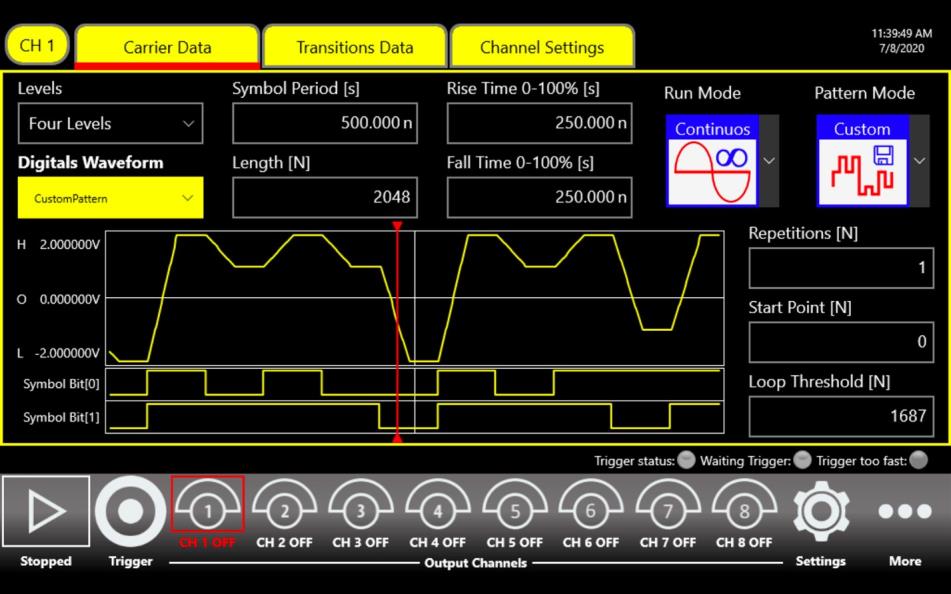
Many failures of digital and high-speed serial interfaces have an analog cause. A receiver that passes with clean square-wave stimulus can fail when edges slow down, when overshoot appears on a transition, or when two inputs switch at slightly different times. Characterizing that behavior needs a stimulus whose analog properties are set deliberately. In the serial pattern mode the bit pattern exercises a protocol or a logic function, and the rise and fall time, overshoot, voltage levels and channel-to-channel timing are set to the conditions the device will see in its application. PRBS and custom stress patterns apply the same method to serial links: the stimulus is degraded in steps until the receiver begins to make errors, and that point is its margin. The eye diagram of Figure 2 is where these effects appear together.
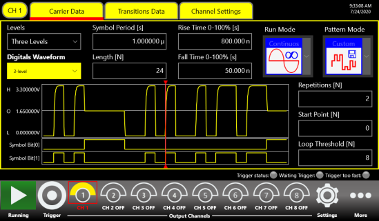
Figure 1. Measured: the serial pattern interface on an eight-channel instrument, set to three levels (0 V, 1.65 V and 3.3 V), a 1 µs symbol period, 800 ns rise and 50 ns fall (0 to 100%) and a 24-symbol pattern, with the two symbol-bit streams below.
Figure 1 shows a three-level pattern and the two symbol-bit streams that encode it. Multilevel patterns matter here as much as the symbol rate. On the Model 675, and on the Model 686 with the 686-PAT option, a custom pattern uses two, three or four levels, so besides a logical 0 and 1 a channel can emulate a tristate buffer or a weak 0 on an undriven bus. One pattern can then reproduce bus contention, level shifts between logic standards, and the multiplexed address and data behavior of a real board. For semiconductor and logic-gate work the same control shortens the setup of reliability and failure-analysis characterization.
Capabilities
The serial pattern mode inherits the analog front end of the instrument it runs on, and the three models differ substantially. Table 1 lists the values from each model's datasheet. Two differences matter most. The Model 675 offers the widest voltage window: up to 6 Vpp into 50 Ω (12 Vpp with the HV option) and a baseline offset of ±3 V (±6 V with the option), with the amplitude doubling into a high-impedance load. With the HV option it therefore places a 0 V to 12 V logic swing on a high-impedance input; into 50 Ω the window is ±6 V. The Models 685 and 686 trade amplitude for speed: 5 Vpp into 50 Ω with a ±2.5 V offset, at symbol rates up to 1.5 Gbaud and 6.5 Gbaud. Each transition between levels is given its own shape (Figure 4): a linear ramp, an RC-type exponential, or an edge with a defined overshoot.
Table 1. Serial pattern mode by model, from each model's datasheet.
| Specification | Model 675 | Model 685 | Model 686 |
|---|---|---|---|
| Pattern mode | Serial Pattern Generator (optional) | Serial Pattern Generator | Pulse Pattern Generator, option 686-PAT |
| Analog channels | 2, 4 or 8 | 2, 4 or 8 | 2 or 4 |
| Vertical resolution | 16 bit | 16 bit | 14 bit |
| Maximum symbol rate | 300 Mbaud | 1.5 Gbaud | 6.5 Gbaud |
| Custom pattern memory | 2 Mbit (2 levels); 1 MSymbols (3 or 4 levels) | 2 MSymbols | 12 Mbit (2 levels) or 6 MSymbols (3 or 4 levels) on 2-channel models; 6 Mbit or 3 MSymbols on 4-channel models |
| Amplitude, single-ended into 50 Ω | 0 to 6 Vpp (12 Vpp with HV option) | 0 to 5 Vpp | 0 to 5 Vpp (686-2C-SE, 686-4C-SE) |
| Offset into 50 Ω | ±3 V (±6 V with HV option) | ±2.5 V | ±2.5 V |
| Calculated bandwidth, True Arb (0.35 / rise time) | ≥ 318 MHz | ≥ 2 GHz | ≥ 5 GHz single-ended |
| Channel-to-channel skew resolution, True Arb | ≤ 5 ps | 100 fs | 100 fs (on 4-channel models, between the CH1/CH2 and CH3/CH4 pairs) |
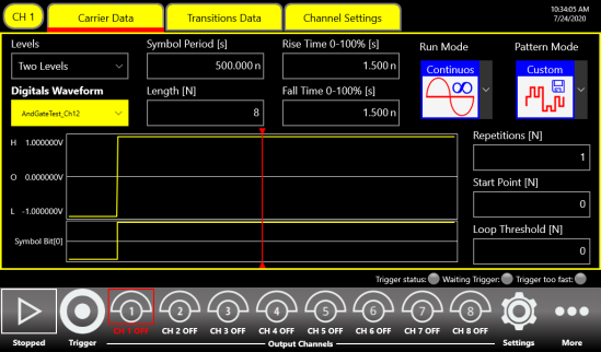
Pattern memory and symbol rate scale with the model (Table 1). The 675 holds 2 Mbit of two-level custom pattern at up to 300 Mbaud, the 685 holds 2 MSymbols at up to 1.5 Gbaud, and the 686 with 686-PAT holds up to 12 Mbit at up to 6.5 Gbaud. All three generate PRBS as well as custom patterns; the 675 and 686 list PRBS-7, 9, 11, 15, 23 and 31. The shortest programmable transition (0 to 100%) is 1.5 ns on the 675 and 150 ps on the 686. On the 675 and 686 a pattern runs continuously, in triggered or gated bursts, or with AM, FM, PM, FSK or PSK applied to it; the 685 modulates the pattern with internal or external signals to add jitter or ripple.
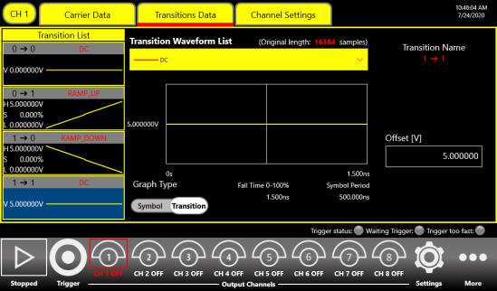
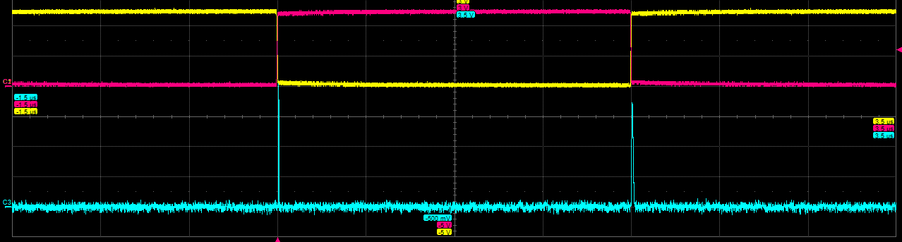
The Models 675 and 685 come with two, four or eight analog channels, and the 686 with two or four. Channel-to-channel skew is specified in True Arb mode, with a resolution of 5 ps or better on the 675 and 100 fs on the 685 and 686 (Table 1). For wider systems the 685 synchronizes up to four units over its dedicated bus, for 32 analog and 128 digital channels, and the 686 synchronizes up to four units for 16 analog and 128 digital channels. Wide buses, multi-input logic gates and multi-lane serial test then run from one timebase. Figure 5 shows two pattern channels switching in opposite directions at the same instants, with a third trace that shows a narrow spike at each transition. Patterns are built on the touchscreen or imported, and the instruments are controlled remotely over Ethernet (LAN, USB-TMC and GPIB on the 685 and 686).
Supported models
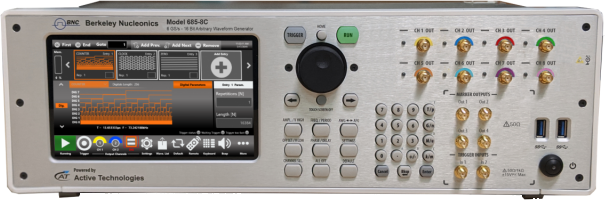
The serial pattern mode runs on three Berkeley Nucleonics arbitrary waveform generators, all through the Simple Rider touchscreen interface (Figure 6 shows the Model 685). On the Model 675 it is an option, and it gives the widest voltage window, to 12 Vpp into 50 Ω with the HV option, for logic-family and level-shifting tests at up to 300 Mbaud. The Model 685 runs it at up to 1.5 Gbaud with 16-bit resolution and 5 Vpp into 50 Ω. On the Model 686 the 686-PAT option adds the Pulse Pattern Generator mode, at up to 6.5 Gbaud with 14-bit resolution and transitions as short as 150 ps.
Choose the model by the symbol rate, voltage window and channel count the device under test requires.
Talk to an application engineer
Berkeley Nucleonics can help you match a Model 685, Model 675, or Model 686 configuration to your serial pattern, PRBS, and digital interface test requirements. Call 800-234-7858 or email info@berkeleynucleonics.com.
For a quick question, chat with an engineer at berkeleynucleonics.com.
Ask now → Chat with our assistant and get an answer in seconds.