Switching time is not settling time
The two phrases describe different intervals, and a timing budget needs both. Switching time is the interval from the command to change frequency until the source begins producing the new frequency. Settling time is the longer interval until the output is usable, meaning the frequency has converged to within a stated tolerance and the amplitude has stabilized. A source can report a fast switching number and still be unusable for a measurement until settling completes.
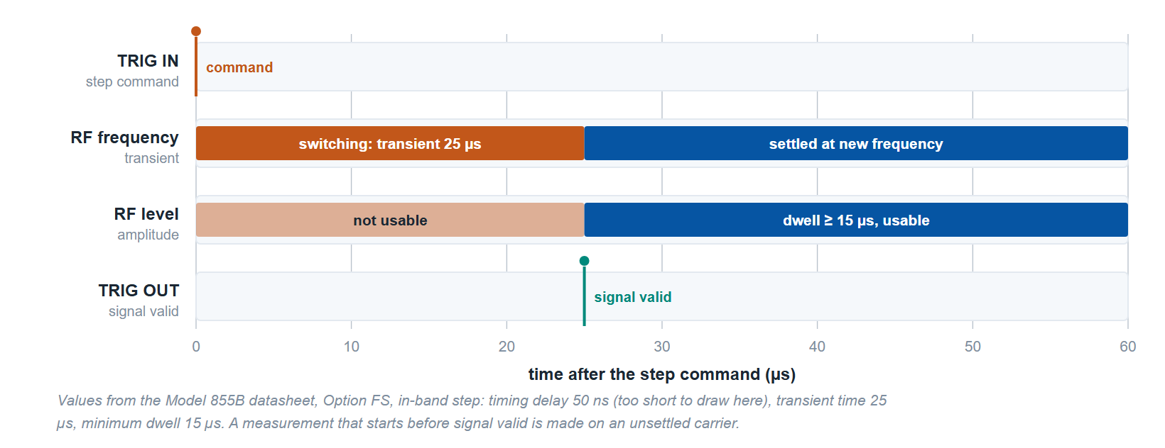
A meaningful agility specification therefore states both the time and the tolerance: settled to within a given frequency error and a given amplitude error. When you compare two sources, confirm that the numbers are quoted against the same settling criteria. A 5 microsecond figure measured to a loose tolerance is not equivalent to a 5 microsecond figure measured to a tight one.
What sets the limit
The dominant limit on switching speed in a synthesized source is the phase-locked loop. After a frequency command, the loop must reacquire lock, and the loop bandwidth governs how quickly that happens. A wider loop settles faster but tends to admit more close-in phase noise, so there is a direct tension between agility and spectral purity. Designers manage this with multi-loop architectures, direct digital synthesis, and dedicated fast-tuning paths.
This is why agility is usually offered as an option rather than a fixed property. The standard configuration favors a clean spectrum. A fast-switching option, often labeled FS, and an ultra-fast option, often labeled UFS, reconfigure the tuning path to settle in a few microseconds, or 1 µs on the Model 875-04 with Option UFS. Some sources add a dedicated fast control port that bypasses the normal command parser to shave latency off every step.
Why agility matters: radar, EW, ATE
In radar, pulse-to-pulse frequency agility spreads energy across the band, which makes the emitter harder to detect and to jam. The source has to land on each new frequency, settled and clean, inside the pulse repetition interval. If settling eats into the dwell, range and Doppler performance degrade.
In electronic warfare, a threat-simulation or jamming scenario may require the source to reproduce an agile emitter that retunes thousands of times per second. The faster and more deterministic the switching, the more faithfully the scenario is reproduced. Slow or jittery switching limits how dense and how realistic a threat environment can be.
In automated test equipment, switching speed is throughput. A production line that measures a device at dozens of frequencies multiplies every microsecond of settling by the number of points and the number of units. At 1,000 frequency points per device, a 500 µs step costs 0.5 s of switching per unit and a 5 µs step costs 5 ms.
How Berkeley Nucleonics sources compare
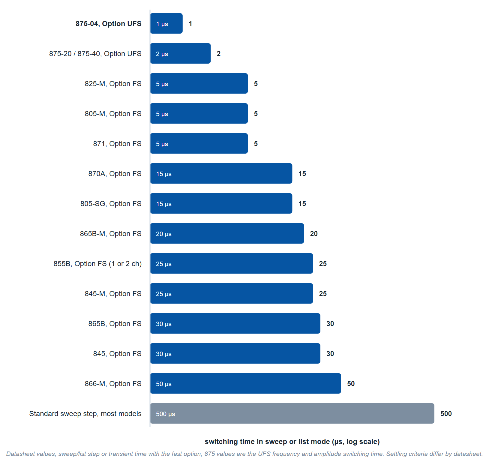
Table 1 lists the switching figures from the current datasheets and the options that enable them. As with phase noise, confirm the exact settling criterion against the datasheet before committing to a timing budget.
| Model | Frequency range | Standard | With fast option | Notes |
|---|---|---|---|---|
| 825-M | 100 kHz to 20 GHz (8 kHz with Option 8K) | 200 µs (500 µs in sweep mode) | 5 µs (10 µs in sweep mode), Option FS | Option FS adds the Fast Control Port; up to 4 phase-coherent channels in 1U (825-M-20-X) |
| 805-M | 100 kHz to 22 GHz | 500 µs sweep step | 5 µs typical, 10 µs maximum, Option FS | Flange-mount module, 1.0 lb |
| 845-M | 10 MHz to 20 GHz | 180 µs | 25 µs, Option FS | Flange-mount module |
| 865B-M | 100 kHz to 40 GHz | 500 µs | 20 µs, Option FS | Desktop module |
| 855B | 300 kHz to 40 GHz | 500 µs | 25 µs for 1 or 2 channels, 50 µs for 3 or 4, in band, Option FS | Up to 4 channels in 1U; Option PHS for phase-coherent switching |
| 870A | 10 MHz to 54 GHz | 500 µs | 15 µs, Option FS | 1 to 4 channels |
| 871 | 10 MHz to 51 GHz | 100 µs (500 µs sweep step) | 3 µs typical, 5 µs maximum, Option FS | 1 to 4 channels |
| 875 | 10 MHz to 40 GHz | 500 µs | 1 µs (875-04) or 2 µs (875-20, 875-40), Option UFS | Vector source; frequency and amplitude switching time |
Each figure is the datasheet's sweep or list step time, or its frequency and amplitude switching time, and each datasheet defines its own settling criterion. The 875 values are frequency and amplitude switching times with Option UFS. Match the specification to the timing the application depends on.
Choosing the right agility
Start from the dwell or test budget, not the headline number. Decide how settled the output must be, then work backward to the switching figure and the option that delivers it. For a multi-emitter EW scenario or a fast scanning radar, ultra-fast switching and a dedicated control port are the options that matter. Where the timing budget allows it, check the cost of the option in phase noise: on the 855B, Option PHS raises phase noise at offsets of 100 Hz and above by typically 10 dB between 1.1 and 10 GHz.
To match a source and its fast-switching options to your dwell, test rate, or threat density, contact Berkeley Nucleonics at info@berkeleynucleonics.com or 800-234-7858. The full family overview is on the RF & Microwave Signal Generators documentation page.