The Mission
Time-of-flight ranging measures distance by measuring time. A laser fires, light travels to a target and back, and a detector records when it returns. The accuracy of the range depends directly on the accuracy of the timing chain: when the emitter fired, when the detector was armed, and when the counter started. A pulse and delay generator anchors that chain, firing the emitter and arming the receive gate from one synchronized reference.
In a LiDAR test bench or a prototype rangefinder, the generator stands in for the system clock, letting engineers sweep delays, gate out near-field returns, and characterize the receiver against a known timing reference.
The Challenge
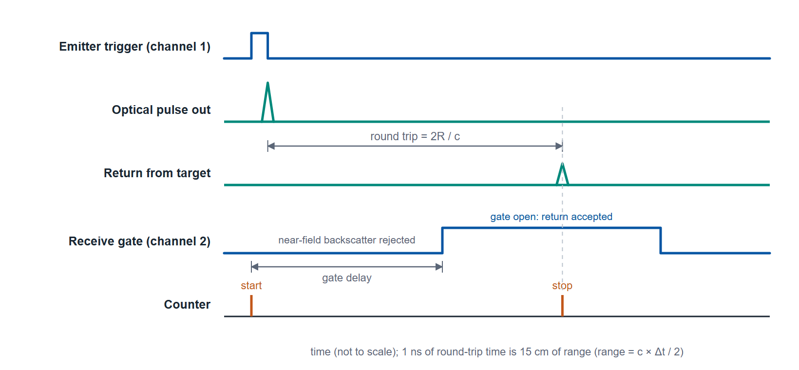
Range resolution is a timing problem. Light covers about 30 cm in a nanosecond, so one nanosecond of round-trip time is 15 cm of range, and picosecond-class delay resolution and low jitter translate directly into centimeter and millimeter ranging precision (Figure 1). The emitter trigger has to be fast and clean so the optical pulse leaves at a well-defined instant. The receive gate has to open at a programmable delay to reject backscatter and arm only over the range window of interest.
Many emitters are not voltage-triggered logic loads but current-driven laser diodes, which need a current pulse rather than a TTL edge. A nanosecond laser-diode driver takes the timing generator's edge as its trigger; emitters that need microsecond or longer current pulses can be driven by a current pulser that the timing generator triggers.
Recommended Berkeley Nucleonics Solutions
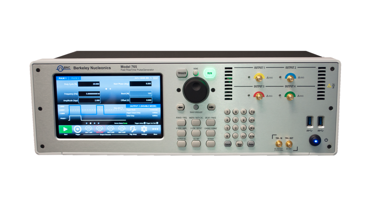
For the timing core, the Model 765 brings 70 ps rise time (20 to 80 percent), 10 ps delay and width resolution, and under 10 ps RMS channel-to-channel jitter across 2 or 4 channels (4 ps RMS period jitter at 200 MHz), fast and fine enough to fire the emitter and step the receive gate at the resolution ranging demands. Where you need the finest delay setting and the lowest jitter for receiver characterization, the Model 745T resolves 1 ps with about 5 ps RMS jitter at delays below 100 ns, and locks to a 10 MHz external clock.
For emitters and loads that take microsecond or longer current pulses, pair the timing generator with a current pulser. The Model 507 supplies adjustable current up to 25 A across 2 or 4 channels, with pulse widths from 100 µs to 100 ms, for high-drive loads and initiators, while the Model 508 delivers repeatable current pulses from 0.1 to 6 A per channel, 5 µs and longer, with 100 ns resolution, 10 ns RMS jitter, and isolated current and voltage monitor outputs. The timing generator sets the schedule; the current pulser drives the load.
Why It Works
Anchoring emission and the receive gate to one reference removes the largest source of ranging error, the relationship between transmit and receive timing. The 765 and 745T provide the picosecond resolution that turns into millimeter range precision, and their programmable gate delay rejects near-field clutter (Figure 2). Splitting voltage timing from current drive lets a laser-diode driver, or the 507 or 508 for longer pulses, handle the load while the timing instrument keeps the schedule exact.
Getting Started
Berkeley Nucleonics application engineers help match channel count, edge speed, jitter budget, and output module to your timing diagram before you order. Send a block diagram or a short description of the events you need to synchronize, and we will return a configuration recommendation.
Email info@berkeleynucleonics.com or call 800-234-7858. Browse the full Pulse & Delay Generator documentation for datasheets, manuals, and ordering guides.