
Drone Spectrum Monitoring
Some RF problems cannot be solved from the ground. A coverage gap on the far side of a ridge, an interferer somewhere across a sprawling industrial site, a signal that only shows itself a hundred meters up: these are hard to reach with a person and a handheld. The terrain is the obstacle, and walking it is slow, sometimes impossible.
Flying the measurement changes the geometry. From altitude, a single pass can survey what would take a ground team days, and it sees over the obstructions that block line of sight at street level. The catch is payload. A drone has a tight weight and power budget, and every gram of instrument trades against flight time and stability. Bolt a benchtop analyzer to a small UAV and it will not leave the ground.
So the requirement is specific. The sensor has to be light enough to fly, draw little enough power to last the mission, and still produce position-tagged spectrum data that holds up as a map.
How the ICX-Series USB module solves it
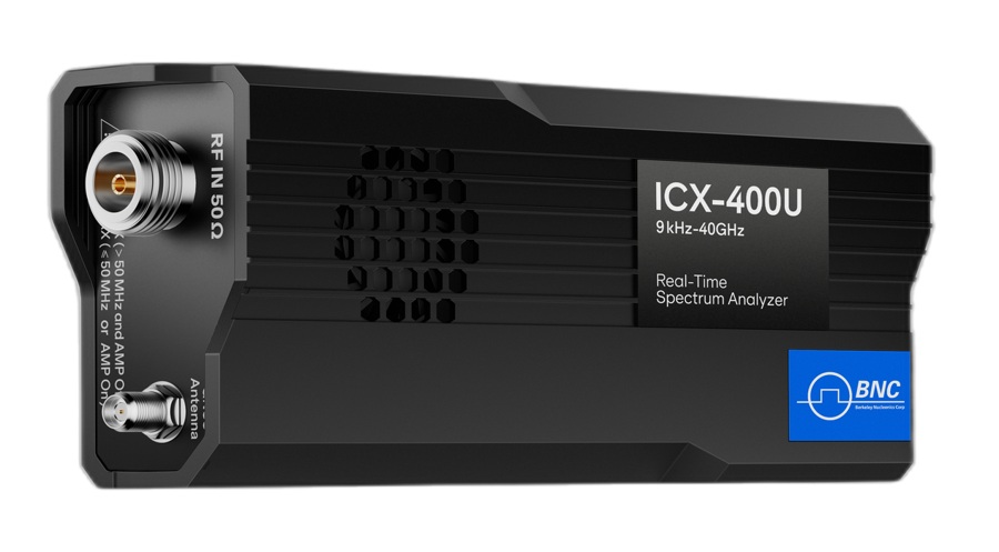
The ICX-Series is a USB core module rather than a boxed instrument, and that form factor is what makes airborne work practical. The ICX-400U USB module weighs under 420 g and measures 139 x 68 x 31 mm; the ICX-200U shares the form factor. It draws 10 to 14 W from a 5 V, 2 A Type-C supply, which a companion computer or a small power module on the airframe can provide for a mission.
Position comes from GNSS: an external GNSS for the module (options 21 to 23, with 1PPS synchronization to ±100, ±75 or ±50 ns) or the flight controller’s own receiver. The companion computer logs spectrum and coordinates together through the API, so the output is a geo-referenced layer rather than a bare sweep. Fly a grid or a perimeter and the data assembles into a picture of where energy is across the area, with altitude and location attached to each reading.
The SpectraCore software drives the capture, and the API (C/C++, C#, Python, MATLAB, Qt and LabVIEW, on Windows and on Linux for x64 and AArch64 hosts) lets the flight computer command the receiver, pull results, and stream them to a ground link. The recorded, position-tagged sweeps feed the same mapping and geolocation tools used on the ground.
Which models and accessories fit

For airborne spectrum monitoring, the clear fit is the ICX-Series. Its weight, power profile, and USB interface are exactly what a UAV integration needs, and nothing else in the line packs the real-time engine into a payload this small. It mounts to a companion computer such as a single-board Linux carrier, takes a GNSS feed, and reports position-tagged spectrum throughout the flight.
Antenna choice depends on the survey. A broadband omnidirectional element suits wide-area mapping, where the goal is to detect whatever is present across the footprint. When the mission shifts toward locating a specific emitter, the RFA-3100-N directional antenna (500 MHz to 10 GHz, 5 dBi typical gain) adds bearing, supporting airborne direction finding as the aircraft maneuvers. It weighs 680 g, more than the receiver, and adds wind load, so check both against the airframe’s payload limit.
The receiver pairs naturally with mapping and geolocation software. Position-tagged sweeps become coverage layers, and repeated passes sharpen an emitter fix through changing geometry, something only flight makes easy. The ground-based ICX-FieldHawk handheld and ICX-FieldHawk-R IP68 receivers complement the airborne kit for follow-up work once a survey narrows the search area.
| Requirement | Recommendation |
|---|---|
| Airborne RF sensor payload | ICX-Series USB module (ICX-200U or ICX-400U), under 420 g, 10 to 14 W |
| Wide-area coverage mapping | Broadband omnidirectional antenna |
| Airborne emitter location | RFA-3100-N directional antenna |
| Position tagging | External GNSS (options 21 to 23) or the flight controller, logged with the spectrum data by the companion computer |
Recommended configuration
Start with an ICX-Series module on a companion computer, fed by GNSS, logging spectrum and position together through the API. Use a broadband omnidirectional antenna for wide-area mapping flights, and keep an RFA-3100-N on hand for directional passes when a target needs locating. The payload is under 420 g plus antenna, draws 10 to 14 W, and lands with position-tagged spectrum data ready for mapping.
Payload weight, power, and antenna mounting all interact with your airframe. Contact a Berkeley Nucleonics applications engineer at info@berkeleynucleonics.com or 800-234-7858 to scope an ICX-Series payload for your platform.
For a quick question, chat with an engineer at berkeleynucleonics.com.