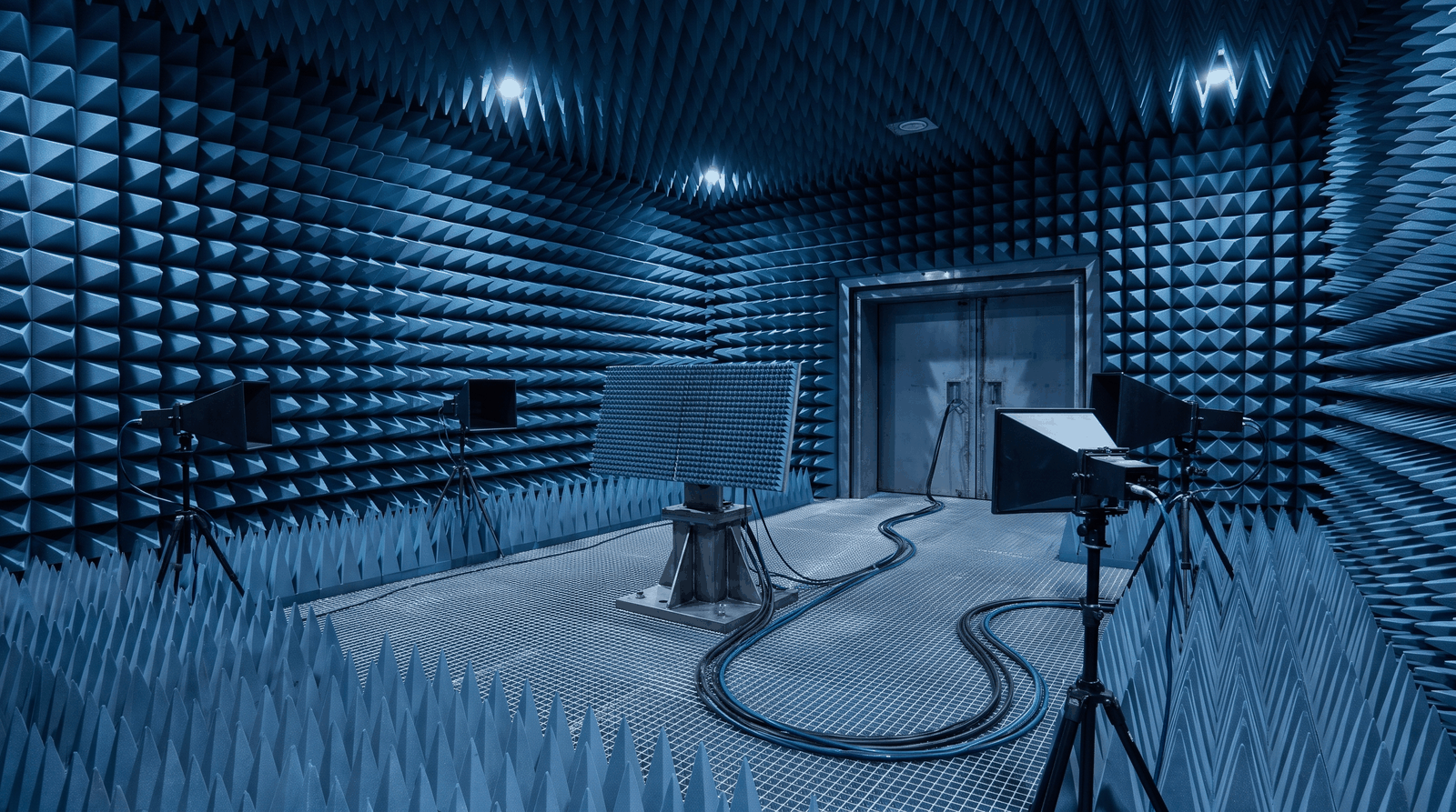
Radar & EW Simulation
Radar target generation and electronic-warfare threat emulation share a hard requirement: the test signal has to look like the real world. A radar receiver under test expects returns that carry the right delay, Doppler, and amplitude for a moving target, and an EW system expects a sky full of emitters that switch, sweep, and hop the way real threats do. Reproducing that in the lab means synthesizing chirps, frequency-agile pulses, complex pulse trains, and multi-emitter scenes with the timing fidelity of the systems they stand in for.
The waveform generator sits at the center of that bench. It feeds the radar receiver, the seeker, or the EW processor a controlled stimulus so engineers can measure detection, tracking, and discrimination against a known truth. When the bench has to recreate a layered threat environment, the generator carries the whole scene, which is why its bandwidth, memory, and channel count set the ceiling on what the lab can test.
The challenge
Modern radar and EW work pushes a waveform generator on several axes at once. Direct or wideband IF and RF synthesis needs a high sample rate and the analog bandwidth to carry it, because a narrow instrument cannot represent a wide chirp or a fast-rising pulse without distorting the very feature under test. Long, non-repeating scenarios need deep memory, since a realistic engagement runs far longer than a short loop and any obvious repeat gives the receiver under test a pattern to lock onto.
Agility is the next demand. Frequency-agile pulses and pulse-to-pulse hopping require fast switching between waveform segments with no settling artifacts between them. Clean edges and low jitter matter because the timing of a pulse defines its range, and any jitter on the generator floor blurs the measurement. Finally, angle-of-arrival and multi-emitter scenes need tight synchronization across channels and across units, so that several phase-coherent outputs can stand in for spatially separated emitters with a known, stable relationship.
These requirements interact. A wide chirp needs sample rate and analog bandwidth, a long engagement needs memory at that sample rate, and a multi-emitter scene needs both on several synchronized channels. The sections below give the Model 686 figure for each, with its condition, so a scenario can be sized against them.
How the Model 686 solves it

The Berkeley Nucleonics Model 686 (Figure 2) samples at up to 20 GS/s with 14-bit vertical resolution. In True Arb mode its measured 3 dB bandwidth is 5.8 GHz (sin(x)/x compensated). The Nyquist frequency at 20 GS/s is 10 GHz; the analog response, not the sample rate, sets the usable band. In AFG mode it generates sine waves to 6.5 GHz on the single-ended models: 5 Vpp to 3.5 GHz, 4 Vpp to 4.5 GHz and 3 Vpp to 6.5 GHz into 50 Ω. Arbitrary waveforms within the 5.8 GHz band cover wideband IF and L-band and S-band signals directly, without an external upconverter in the chain.
In True Arb mode at full rate, CH1 holds up to 9.6 Gsamples (CH1 and CH3 on the 4-channel models): 0.48 s of continuous waveform at 20 GS/s. The other channels are shorter, 1.17 Msamples on CH2 of the 2-channel models (58.5 µs at 20 GS/s) and 589 ksamples on CH2 and CH4 of the 4-channel models (29.45 µs). A long non-repeating engagement belongs on CH1 or CH3; on the short-memory channels, a multi-emitter scene is built from sequencer entries (up to 16,384) that repeat or branch. Rise and fall times are 50 ps or less (20% to 80%) and 70 ps or less (10% to 90%), at 1 Vpp single-ended. Random jitter on a clock pattern is under 2 ps rms; Trigger In to output jitter is 0.29 × DAC clock period rms in True Arb mode, 14.5 ps rms at 20 GS/s, equivalent to 2.2 mm of radar range.
For multi-channel and multi-emitter scenes, up to four units synchronize over the dedicated sync bus (QSFP Sync In and Sync Out, RIDER-686-SYNC cable); four 4-channel units give 16 analog and 128 digital channels. Within one chassis, channel-to-channel skew is adjustable over 0 to 1.63 µs with 100 fs resolution (between CH1 and CH2 on the 2-channel models; between the CH1/CH2 and CH3/CH4 pairs on the 4-channel models), with ±(1% of setting + 20 ps) accuracy and under 20 ps initial skew. At 5 GHz, 100 fs is 0.18° of phase and 20 ps is 36°, and alignment between units is set during calibration rather than specified, so for angle-of-arrival work, measure the relative phase of every output at the receiver input during calibration and set the skew from that measurement. Fast switching between sequence entries, for frequency-agile and hopping behavior, uses the 686-FSS Fast Sequence Switch option.
| Requirement | Model 686 capability |
|---|---|
| Wideband IF / RF synthesis | 20 GS/s sample rate; 5.8 GHz measured 3 dB bandwidth (True Arb, sin(x)/x compensated); sine to 6.5 GHz (AFG) |
| Long non-repeating scenarios | 9.6 Gsamples on CH1 and CH3; 1.17 Msamples (CH2, 2-channel models) or 589 ksamples (CH2 and CH4, 4-channel models) |
| Pulse timing fidelity | Rise / fall ≤ 50 ps (20% to 80%, 1 Vpp single-ended); random jitter on a clock pattern < 2 ps rms; Trigger In to output jitter 14.5 ps rms (True Arb, 20 GS/s) |
| Segment agility | Sequencer up to 16,384 entries; fast switching with the 686-FSS option |
| Multi-emitter and AoA scenes | Up to 4 units synchronized: 16 analog + 128 digital channels |
Recommended configuration
For a radar target generator or a single-threat EW bench, one Model 686 drives the wideband IF or direct RF path for chirp, agile-pulse and pulse-train work within the 5.8 GHz band, with the long scenario on CH1 (or CH3). Add the 686-FSS option where the scenario switches segments pulse to pulse. For angle-of-arrival emulation and dense multi-emitter scenes, synchronize up to four Model 686 units so the channel count matches the emitters and directions the scenario calls for, up to the full 16 analog and 128 digital channel configuration, and calibrate the relative phase of every output at the receiver input. On the 4-channel models, pair the digital channels (686-8DIG, 686-16DIG or 686-32DIG license) with the analog outputs to mark events and drive switches in step with the RF.
Talk to an application engineer
Berkeley Nucleonics can help defense and aerospace test labs match a Model 686 configuration to a radar or EW scenario, from a single target generator to a synchronized multi-emitter system. Call 800-234-7858 or email info@berkeleynucleonics.com.
For a quick question, chat with an engineer at berkeleynucleonics.com.
Ask now → Chat with our assistant and get an answer in seconds.