Analog modulation versus vector modulation
An analog Signal Generator varies one property of the carrier at a time: amplitude for AM, frequency for FM, or phase for PM. That is enough for many tasks, and it keeps the architecture simple. It is not enough for modern digital communications or for realistic radar and electronic warfare signals, where amplitude and phase change together in arbitrary patterns that no single analog parameter can describe.
Vector modulation solves this by controlling amplitude and phase simultaneously and independently. Any point in the complex plane becomes reachable, so any waveform that can be written as a sequence of amplitude and phase values can be generated.
The I/Q representation
Vector modulation works in terms of two components. The in-phase component, I, is the part of the signal aligned with a reference carrier. The quadrature component, Q, is the part shifted ninety degrees from it. Together I and Q define a vector whose length is the instantaneous amplitude and whose angle is the instantaneous phase. Steer that vector over time and you have produced an arbitrary modulated signal.
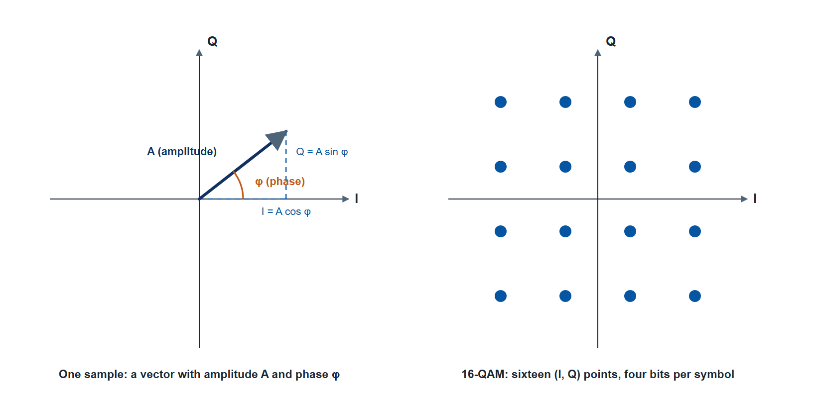
This representation is powerful because complex schemes reduce to streams of I and Q samples. A 256-QAM constellation, an OFDM symbol, a chirped radar pulse, or a frequency-hopped waveform all become sequences of I/Q values fed to the modulator. The Model 875 carries a digital I/Q modulator fed by an internal baseband generator, so it plays custom I/Q waveforms from memory, generates QAM from 8QAM to 4096QAM with Option IVM, adds the avionics formats DME, VOR, ILS and marker beacon with Option AVIO, and adds Gaussian noise at a set carrier-to-noise ratio with Option AWGN.
Wideband modulation and deep memory
Two properties decide how demanding a vector source can be: modulation bandwidth and memory depth. Wide modulation bandwidth lets the source reproduce signals that occupy large instantaneous spans, which matters for wideband radar, modern wireless, and realistic interference. Deep waveform memory lets it play long, non-repeating sequences without looping, which matters when a short repeating pattern would betray the simulation or fail to stress the device under test.
The 875 has a 400 MHz RF modulation bandwidth, a 16-bit baseband generator at up to 500 MS/s and 512 MS of waveform memory, and adds linear chirp, intra-pulse modulation and pulse shaping. The 875 therefore controls the modulation within each pulse as well as its envelope.
Pulse descriptor word playback for EW
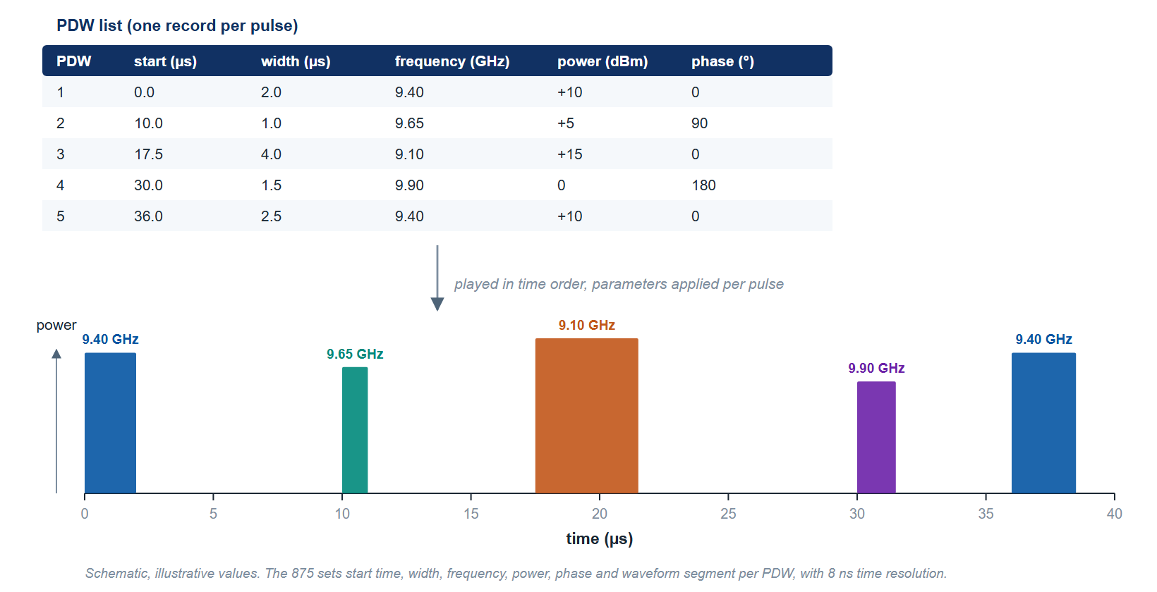
Electronic warfare test uses signal environments with many simultaneous emitters. A modern scenario may contain many emitters, each with its own frequency, power, pulse width, and timing, all changing as the scenario evolves. Describing that environment in waveform samples would be impractical. The pulse descriptor word, or PDW, describes each pulse by its parameters instead.
A PDW is a compact record of one pulse: on the Model 875, its start time, pulse width, frequency, power, phase and waveform segment. A list of PDWs describes an entire emitter, or a whole emitter environment, as a stream of instructions rather than raw samples. The Model 875 plays PDW lists loaded through its GUI or by SCPI command (list mode, up to 1024 PDWs per list, repeated 1 to 65 million times or continuously, Option PDW), and with Option FCP it accepts PDWs streamed through the Fast Control Port while the simulation runs (stream mode, through a buffer of up to 1024 PDWs), so a scenario can react. This is how one source reproduces an agile, multi-emitter threat picture for receiver and EW system test.
Model 875 vector capabilities
Table 1 lists the vector and modulation capabilities most relevant to communications and EW work, from the current datasheet. Confirm option availability and exact figures against the datasheet before ordering.
| Capability | Model 875 |
|---|---|
| Frequency range | 10 MHz to 4, 6, 12, 20 or 40 GHz (875-04, 875-06, 875-12, 875-20, 875-40); 100 kHz with Option 100K |
| Channels | 1 in the portable enclosure; 1 to 4 phase-coherent channels in a 2U rack unit (875-X) |
| Modulation | I/Q from internal memory; chirp; pulse, AM, FM and PM (Option MOD); 8QAM to 4096QAM at up to 200 MS/s (Option IVM); DME, VOR, ILS and marker beacon (Option AVIO); additive white Gaussian noise (Option AWGN); external analog I and Q to 50 MHz (Option AIQ) |
| Baseband generator | 16-bit samples, 10 Hz to 500 MS/s, 512 MS memory, 400 MHz RF modulation bandwidth, 85 dBc typical (65 dBc minimum) image sideband rejection |
| PDW playback | List mode loaded from the GUI or by SCPI (Option PDW); stream mode through the Fast Control Port (Options PDW and FCP) |
| Switching time | 500 µs standard; 1 µs (875-04) or 2 µs (875-20, 875-40) with Option UFS |
| Output power | -20 dBm minimum; maximum +18 dBm (875-04), +15 dBm (875-06) or +17 dBm (875-20 and 875-40 below 20 GHz); -55 dBm with Option PE4 (875-04, 875-06, 875-12), -90 dBm with Option PE, -120 dBm with Option PE2 |
| Phase noise, 1 GHz carrier, 1 kHz offset | -130 dBc/Hz typical at +10 dBm; Option LN improves the 10 Hz figure from -87 to -98 dBc/Hz typical |
Several capabilities above are options, including PDW, FCP, MOD, AVIO, and the attenuator extensions. Specify the scenario you need to reproduce so the unit is ordered with the right combination rather than retrofitted later.
Plan a vector source
Vector and PDW configuration is best scoped against the signals and scenarios you intend to generate, since the options interact. Berkeley Nucleonics application engineers can map your communications standards or EW threat list onto a Model 875 configuration. For specifications and quotations, contact info@berkeleynucleonics.com or call 800-234-7858. The full family overview is on the RF & Microwave Signal Generators documentation page.