
Illustration: a vehicle-mounted radar and mast at night in open farmland.
1The contested electromagnetic spectrum
Electronic warfare is a fight over information, and that fight happens in the radio spectrum. Whoever sees the spectrum first, and sees it most completely, holds the advantage. The problem is that the modern spectrum is crowded, fast, and adversarial. A single band can hold commercial communications, friendly waveforms, civilian radars, and the emitters an operator needs to find. The emitters that matter most are often designed to be hard to see.
Adversaries know that a strong, steady carrier is an invitation. So they make their emissions brief, faint, and unpredictable. A search radar might dwell on a sector for only a few microseconds before stepping elsewhere. A frequency-agile data link might hop hundreds of times a second across a wide band. A pop-up threat might key up for a fraction of a second, do its work, and go quiet before a slow instrument finishes looking somewhere else. These are low-probability-of-intercept emissions, and they are designed to defeat a swept analyzer’s way of looking at the band.
Electronic support and signals intelligence both depend on one prior capability: detecting the emission in the first place. An emitter that is never seen cannot be classified, geolocated, jammed, or added to a threat library. For the EW operator, the question is not only what the spectrum contains. It is whether the instrument can guarantee that a fleeting signal will not slip through unobserved.
2Why swept analyzers miss threats
A traditional swept-tuned spectrum analyzer builds its display by tuning a narrow filter across the band one frequency segment at a time. It looks at a slice, measures the power, steps to the next slice, and repeats. To cover a wide span the instrument has to make many of these steps, and each step takes time. While the analyzer is measuring one part of the band, every other part of the band is unobserved. That unobserved interval is sweep blind time, and it is the structural weakness an adversary exploits.
Consider the arithmetic. If an instrument needs tens of milliseconds to sweep a wide span, a pulse that lasts a few microseconds will, with overwhelming probability, occur while the sweep is looking somewhere else. The energy was present in the air. The analyzer was not pointed at that frequency at that instant. The signal was not faint or hidden. It was missed because of when the measurement happened, not because of how strong it was.
Frequency-agile emitters compound the problem. A hopping transmitter that changes frequency faster than the analyzer completes a sweep will paint the display with disconnected fragments, or with nothing at all. The operator sees an occasional speckle and cannot tell whether it is a real emitter, a glitch, or noise. The threat hides not by being quiet, but by never being in the same place twice when the instrument happens to look.
3Real-time capture and 100% probability of intercept
A real-time spectrum analyzer removes the blind time. Instead of tuning a filter across the band, it digitizes the entire instantaneous bandwidth at once and runs a continuous stream of fast Fourier transforms on the incoming samples. The transforms are computed back to back, with no dead interval between them, so every fraction of energy that enters the front end is converted into a spectrum. There is no moment when part of the band is unobserved. The band is always being processed.
This is what makes a real-time analyzer suitable for electronic warfare. With gapless, overlap-free FFT frames the instrument guarantees that any signal lasting at least two frames is captured at full amplitude. That minimum is the probability-of-intercept duration, usually written as POI. On the ICX-FieldHawk it is published as arithmetic, POI = 2 × N × D × 8 ns for an N-point transform at decimation D: 0.512 µs with a 32-point transform at decimation 1, and 32.768 µs at 2,048 points, on the 9.5, 20 and 40 GHz models.
POI is the figure that matters for pop-up threats. A pop-up emitter that keys for a few microseconds is invisible to an instrument whose POI is measured in milliseconds, and it is fully captured by an instrument whose POI is shorter than the emission. The shorter the guaranteed POI, the briefer the threat the operator can still see, classify, and act on. In EW the difference between a guaranteed sub-microsecond POI and a best-effort sweep is the difference between an emitter list that is complete for pulses of 0.512 µs and longer and one with a gap of unknown size.
Probability of intercept is the minimum signal duration the analyzer is guaranteed to capture at full amplitude. Lower POI means shorter, more elusive threats are still seen.
4Density and persistence displays
Capturing every spectrum is necessary but not sufficient. A real-time analyzer produces far more spectra per second than an operator could ever read one at a time. The instrument generates tens of thousands to millions of frames per second, and a faint, intermittent emitter would be lost in the blur of a conventional trace. Density and persistence displays solve this by accumulating many transforms into a single picture and coloring each point by how often signal energy appears there.
The effect is that frequency of occurrence becomes visible. A strong continuous carrier and a rare, weak burst both leave marks, but the display distinguishes them by persistence. A signal that hides underneath a stronger one, at the same frequency but present only briefly, separates out as a distinct trace because its rate of occurrence differs. This is how an operator pulls a low-level threat out from under a dominant commercial signal that would otherwise mask it entirely.
For electronic warfare this is the needle-in-the-haystack tool. The haystack is the dense, busy spectrum full of friendly and benign emissions. The needle is the rare, low-power, intermittent emitter that an adversary hoped would blend in. A persistence display brings that needle forward visually, so the operator can recognize a pattern that a single snapshot would never reveal.
5Triggered IQ acquisition
Once an operator knows what normal looks like, the next problem is automation. No one watches a display for hours for a signal that may appear for a millisecond at an unknown time, so the acquisition has to be armed. IQ Streaming mode on the ICX-FieldHawk acquires on multiple trigger methods, and the external trigger input responds up to 500 times per second, so the receiver can be slaved to a direction-finding system, to a radar’s own timing, or to a detection made in the host software.
Each trigger starts an IQ capture of up to 100 MHz bandwidth at up to 125 MSPS into 128 Mbyte of built-in memory; continuous recording runs at up to 25 MHz. Nothing has to be sweeping past the right frequency at the right time, because the whole analysis bandwidth is digitized and the trigger only decides what is kept.
This is the way to catch intermittent and hopping emitters. An emitter that appears only occasionally is recorded at its trigger, and the operator returns to a stored capture of the exact event rather than a memory of a flicker. A frequency-domain condition can be applied on the host: the API delivers each spectrum, and the host’s own code decides when to start a capture, so benign signals are ignored and only the anomalies that matter are recorded.
6Pulse measurement
Detection answers whether an emitter is present. Characterization answers what it is. Radar and many threat emitters are pulsed, and their signatures live in the timing and shape of those pulses. Pulse measurement records the parameters that distinguish one emitter from another, one row per pulse: the same information an electronic-support system carries as pulse descriptor words, or PDWs.
The core parameters are straightforward to state and rich in meaning. Pulse width is how long each pulse lasts. Pulse repetition interval, or PRI, is the time between successive pulses, and its inverse is the pulse repetition frequency. Duty cycle is the fraction of time the emitter is transmitting, the ratio of pulse width to PRI. Intra-pulse modulation describes how the signal changes within a single pulse, for example a linear frequency chirp or a phase code, which is often the most telling fingerprint of a specific radar.
Taken together these measurements let an operator separate a navigation radar from a tracking radar, recognize a known emitter from its modulation, and detect changes in an emitter’s behavior that signal a change in its mode. On the ICX-FieldHawk, Pulse Detection (option 72) tabulates top and base level, rise and fall time, width, repetition interval and duty cycle for each pulse in the record, with the minimum, maximum and mean PRI and width; intra-pulse modulation is read from the recorded IQ. Together they give the analyst both the raw evidence and the compact summary needed to classify and track an emitter over time.
7Frequency-hopping and agile signals
Some of the most demanding EW targets do not sit still in frequency. Frequency-hopping data links and agile radars change their carrier on a fast schedule, deliberately, to resist detection and jamming. A single spectrum snapshot cannot describe such an emitter, because by the time the snapshot is read the signal has already moved.
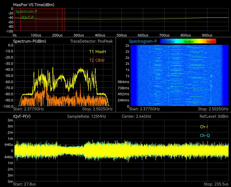
The spectrogram, also called a waterfall, is the right view for these signals. It stacks successive real-time spectra over time, with frequency on one axis, time on another, and amplitude shown as color. A hopping emitter that looks like random speckle on a single trace resolves into a clear pattern on the waterfall, a sequence of dwells stepping across the band. The operator can read the hop set, the order and timing of the frequencies the emitter visits, directly from the picture.
Because the underlying capture is gap-free, the waterfall does not lose hops between frames. Every dwell that lasts longer than the POI is recorded in its correct time and frequency. That completeness is what lets an analyst reconstruct a full hop set, estimate the hop rate, and decide how to respond, whether that means following the emitter, cataloging it, or reporting it.
8IQ record and playback
The decisive advantage of a real-time platform is that it keeps the raw evidence. When the instrument captures IQ data, at up to 100 MHz bandwidth into 128 Mbyte of memory or continuously at up to 25 MHz, it stores the complete in-phase and quadrature samples of the signal, not just a processed picture. That recording contains everything the receiver saw in the captured bandwidth, which means analysis is not limited to what the operator chose to display at capture time.
This changes the work of EW analysis. A mission can be recorded in the field and re-run later in the lab, as many times as needed, with different settings each pass. An analyst can replay an engagement, change the resolution, apply different demodulation, or re-examine a moment that looked unremarkable live and turned out to matter. Nothing is lost to a setting that was wrong at the time, because the raw samples are preserved.
Recorded IQ is also how threat libraries are built. Each well-characterized capture, with its PDWs and modulation analysis, becomes a reference entry that future detections can be matched against. Over many missions the library grows into an institutional record of the emitters in a theater, so that a signal seen once and understood can be recognized instantly the next time it appears.
9Fielding the capability
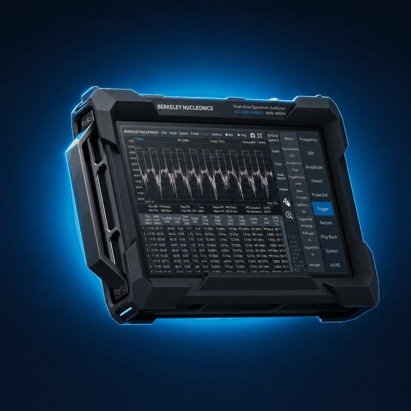
A laboratory analyzer that never leaves the bench cannot do electronic support at the edge. The capabilities above only matter to the EW operator when they fit in a form that survives the field. The ICX-FieldHawk line carries real-time spectrum analysis into forward environments without giving up the performance that makes it useful.
The ICX-FieldHawk-R is the field member of the family: the same measurement engine in an IP68 impact-protected chassis with corner bumpers, with standard 0 to 50 °C operation and optional T1 (-20 to +65 °C) and T2 (-40 to +65 °C) temperature classes. It is intended for forward electronic support and counter-UAS work, where pop-up and agile emitters are the routine targets rather than the exception. An onboard AI compute module is available as option 08, rated up to 117 TOPS (sparse INT8) in the module’s highest power mode; sustained throughput depends on the power mode the enclosure allows, and the open API carries the user’s own models.
The ICX-Series is the USB-form member, designed for embedding into larger systems and for integration with software-defined radio workflows. Where an integrator needs the real-time engine inside a custom platform, a vehicle, or a fixed site, the USB form delivers the same processing in a package that other software can drive.
For direction finding, the RFA-3100-N directional antenna pairs with either receiver to turn a detection into a bearing. Once an emitter is found, the directional antenna lets the operator take the angle-of-arrival measurements that begin the geolocation process. Across the family the coverage spans 9 kHz to 40 GHz with up to 100 MHz of analysis bandwidth, and all of it runs under the SpectraCore software with one API, so the density displays, triggered IQ acquisition, pulse measurement and IQ record described above behave consistently from one form factor to the next.
10Recommended configuration and closing
For a forward electronic support and counter-UAS role, start with the ICX-FieldHawk-R for its sealed enclosure and temperature classes, pair it with the RFA-3100-N directional antenna (500 MHz to 10 GHz, 5 dBi typical gain, azimuth readout) for bearing measurements, and standardize on SpectraCore across the unit so operators see the same density displays, trigger setups, and pulse tables everywhere. Where the requirement is to embed real-time analysis inside a vehicle, a fixed site, or an SDR-based system, choose the ICX-Series USB receiver and drive it from the host platform. In both cases, enable IQ recording from the outset so that every mission feeds the threat library rather than disappearing when the display clears.
The thread through all of it is simple. The threats that matter in electronic warfare are the ones built to be missed. Real-time spectrum analysis is the discipline of not missing them: gap-free capture for a guaranteed probability of intercept, density displays to surface the faint and the rare, triggered acquisition to automate the watch, pulse measurement to identify what was found, and IQ record to study it and keep it. Put that capability in a field form and the operator stops reacting to the spectrum and starts reading it.
Talk to an engineer
To discuss a configuration for your mission, contact Berkeley Nucleonics at 800-234-7858 or info@berkeleynucleonics.com.
For a quick question, chat with an engineer at berkeleynucleonics.com.