Start with frequency reach
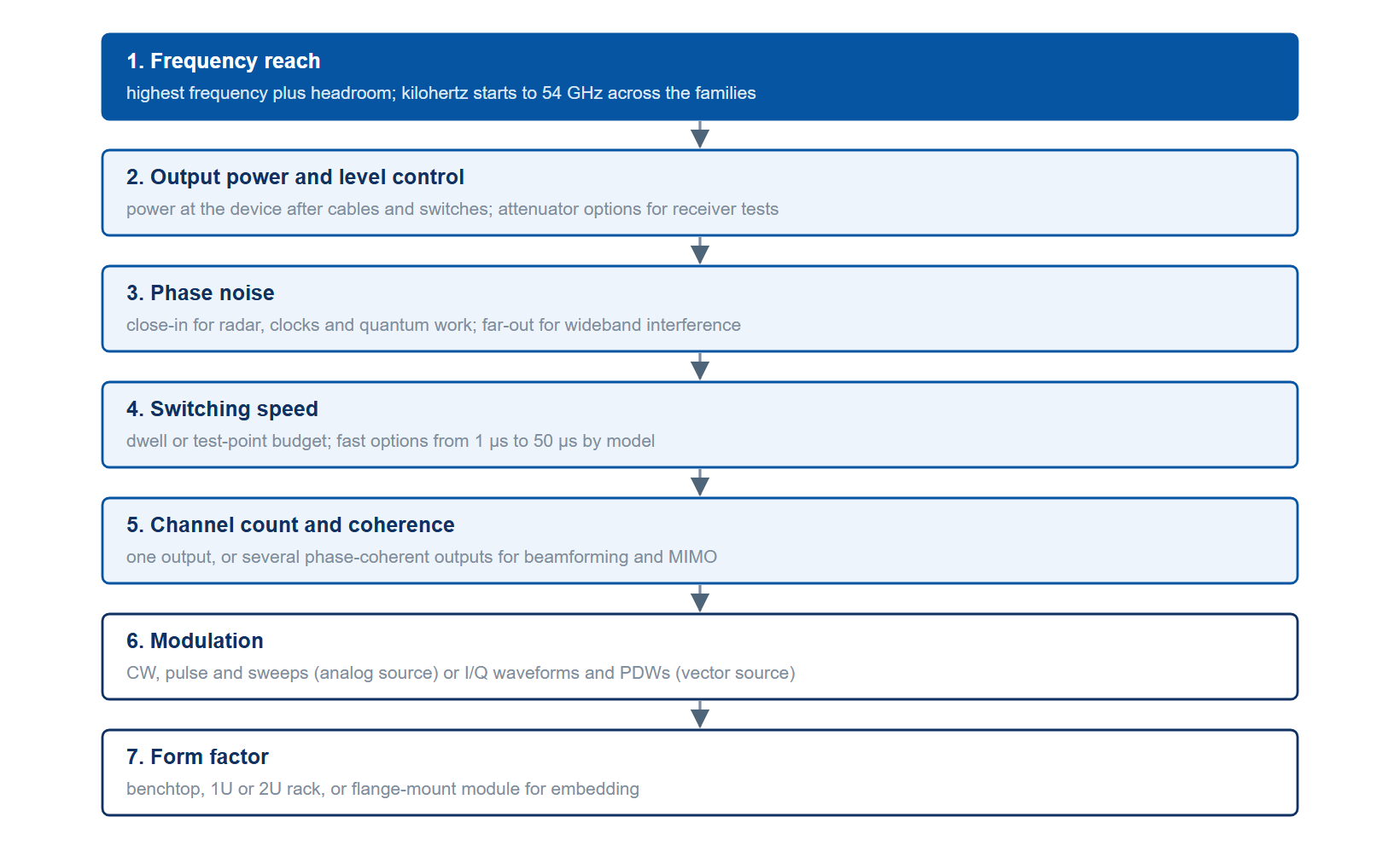
The first filter is the band you need to cover, plus headroom. A source must reach your highest operating frequency with margin for harmonics work and future expansion. Berkeley Nucleonics sources span from kilohertz starting points up to 54 GHz, so the practical question is how high the application needs to go. Buying far more reach than the application requires raises cost without buying capability, while buying too little forces a second instrument later. Pick the top frequency first, then let the other decisions refine the choice within that band.
Output power and level control
Next, fix the power you need at the device under test, after cables, switches, and any attenuation. A receiver test wants clean low-level tones, sometimes well below -100 dBm, which calls for a step attenuator option. A component or amplifier test wants drive: the Model 855B reaches +25 dBm from 100 MHz to 6 GHz, the Model 865B-12 and 865B-20 reach +26 dBm from 10 MHz to 5 GHz, and the Model 805-M module reaches +26 dBm from 1 to 10 GHz. Just as important as the maximum is level accuracy and resolution, since a leveling error propagates straight into every measurement made against the source.
Phase noise, switching speed, and channels
Once the band and power are known, three further decisions narrow the choice. Phase noise sets spectral purity, and the source must be quieter than whatever it tests, with attention to the close-in region for radar and quantum work and the far-out region for wideband interference. Switching speed sets agility, and the right figure depends on your dwell or test budget, with fast and ultra-fast options available where it matters. Channel count decides whether one output suffices or whether you need phase-coherent multi-channel operation for beamforming, MIMO, or phased-array test. These topics each have a dedicated note linked at the close.
Modulation and form factor
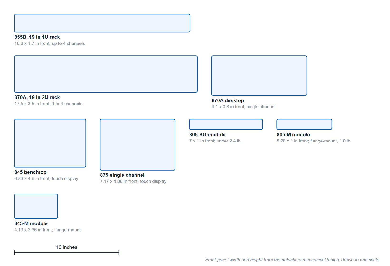
Decide what the signal must do. If you only need clean tones, pulses, and sweeps, an analog source covers the need without an I/Q modulator. If you need digital communications standards, arbitrary I/Q waveforms, or real-time pulse descriptor word playback for electronic warfare, a vector source is required. Finally, decide where it lives: a portable benchtop unit for the lab, a 1U or 2U rackmount for a test system, or a compact flange-mount module for embedding inside OEM equipment. Form factor can decide between two models with similar specifications.
Mapping families to use cases
Berkeley Nucleonics organizes its sources into three families. Signal Generators are the broad analog instruments: benchtop units (the 835, 845, 865B and single-channel 870A with a touch display, the 871 with front-panel knob control), the 870A and 871 also in 2U racks of up to four channels, and the rack-mount 855B, which is controlled from a PC. Synthesizers and sources are compact, agile modules optimized for low noise or fast switching, often for embedding or for multi-channel systems. Vector Signal Generators add I/Q and PDW capability for communications and EW. Table 1 maps each family to the work it suits and links a representative datasheet.
| Family | Best for | Representative models | Datasheet |
|---|---|---|---|
| Signal Generators | General-purpose RF and microwave test, production verification, widest frequency reach, benchtop or rack use | 870A (to 54 GHz), 855B (up to 4 channels in 1U, +25 dBm), 865B | 870A · 855B |
| Synthesizers & Sources | Low-noise local oscillators, fast-switching agile sources, compact and OEM-embedded modules, phase-coherent multi-channel systems | 865B-M (-130 dBc/Hz typical at 1 kHz, 1 GHz carrier), 825-M (5 µs switching with Option FS), 845-M, 805-M | 865B-M · 825-M |
| Vector Signal Generators | Digital communications standards, arbitrary I/Q waveforms, radar and EW emulation with real-time PDW playback | 875 (1 to 4 channels, 10 MHz to 40 GHz) | 875 |
Several models appear capable across categories, and the right answer often depends on a single dominant requirement: the cleanest close-in noise, the fastest switching, the most channels, or vector capability. When two families both fit, let that one requirement break the tie.
A short worked example
Suppose you are building a four-channel phased-array radar test bench up to 20 GHz, you need phase-coherent outputs, and switching speed is critical for agile waveform emulation. Frequency reach rules out the lowest-band parts. Channel count and phase coherence point to the multi-channel synthesizers and to the multi-output 855B. Switching speed favors the 825-M-20-X, four channels in 1U with Option FS for 5 µs switching and the Fast Control Port. If the same bench later needs to inject realistic modulated threats, a Model 875 joins it for the vector and PDW work. The decision falls out of the requirements in order, rather than from any single headline number.
Get a recommendation
The fastest path to the right source is a short conversation about your band, power, noise, agility, and channel needs. Berkeley Nucleonics application engineers will map those onto a specific model and option set. Contact info@berkeleynucleonics.com or call 800-234-7858. For deeper background, see the companion notes on phase noise and spectral purity, switching speed and agility, and vector modulation and PDWs, or browse the full RF & Microwave Signal Generators documentation page.