
Directed-Energy & High-Energy-Laser Systems
High-energy-laser research runs on diode pumps. The large solid-state and fiber laser systems studied in laboratory and industrial settings are pumped by banks of diode-laser bars and arrays, and the optical power those pumps deliver is set by the current driving them. Scaling a system up makes the pump drive a central engineering problem: hundreds of amps, delivered as long quasi-continuous-wave pulses, into arrays that represent a large investment and tolerate very little from a bad pulse. This is research and industrial work, the pump-drive and beam-combining test bench, not a fielded system.
The Directed Energy Division of Berkeley Nucleonics (DEI) builds the laser diode drivers for this work, which run from the 125 A PCO-6131 OEM module to the 450 A PCX-7500-EX, which takes its compliance voltage, up to 110 V, from an external DC supply matched to the diode string.
The challenge
Pumping a large laser at high average power concentrates several hard problems at once. The first is raw current. A bank of diode bars in series can demand hundreds of amps during the pump pulse, and the driver has to source that current with enough compliance voltage to overcome the combined forward drop of a long string. The second is average power. High-energy systems do not pump in brief shots, they pump in long QCW pulses repeated at a duty cycle that keeps the gain medium populated, so the driver has to hold a long, flat current pulse (Figure 1) and dissipate the heat that comes with running near continuously.
Thermal and duty management therefore sit at the center of the design. Push the duty cycle up for more average optical power and the thermal load on both the driver and the array climbs, so the system has to be planned as a whole: current, pulse width, repetition rate, and cooling budgeted together rather than tuned in isolation. The third problem is timing. A beam-combining bench coordinates many pump channels, and if their drivers do not share a clean timing reference the combined output suffers. Stitching together pump drivers, triggers, and monitors from different vendors multiplies the points where that timing chain can break.
The BNC approach
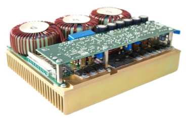
DEI high-current drivers hold long QCW pulses at high current with the compliance to drive deep diode strings. The output is a controlled current source through the full pulse, not only at its leading edge, so a long pump pulse stays flat and the gain medium receives the energy the experiment planned. The PCX-7500-EX datasheet capture shows a 96 µs, 450 A pulse at 8 Hz into a load at 73 V compliance, with a measured rise of 2.564 µs and fall of 2.620 µs against a 7 µs specification. Protection is specified per model: the PCX-7500-EX output connector is interlocked, so the source is disabled when it is removed; the PCO-6131 (Figure 2) disables its output if its +24 VDC supply falls below 18 V, clamps reverse voltage at the diode and stores about 7 J at 125 A; and the PCX-7500-EX and PIM-Mini-200 each operate inside a published safe operating area for current, voltage, pulse width and rate.
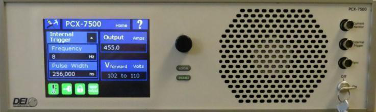
Each driver takes an external trigger, so a multi-channel Digital Delay Generator can set the timing of every pump channel from one timebase. The PCX-7500-EX trigger-to-output delay is 1 µs or less (typical), its cycle-to-cycle jitter is 0.025 µs or less, and its sync output is synchronized to the leading edge of the current pulse; the PIM-Mini-200 trigger-to-output delay is also 1 µs or less (typical). Current monitors on the PCX-7500-EX (170 mV per 100 A, typical), the PIM-Mini-200 (0.500 V at 200 A, typical) and the PCO-6131 (optional PCA-9155 board, 1000 A/V into 50 Ω) let each channel's current be recorded against the same trigger. Berkeley Nucleonics supplies the drivers and the Digital Delay Generators, so a multi-channel pump bench has one support path.
Sizing by model: the PCO-6131 delivers up to 125 A with pulse widths from under 100 ns to DC at up to 100 percent duty, into diode strings with forward voltage up to 20 V. The compact PIM-Mini-200 delivers 25 A to 200 A in 25 µs to 250 µs pulses at up to 200 Hz, into forward voltages from 0 V to 48 V, with its DC input set 12 V above the string's forward voltage; its maximum duty cycle falls to about 0.4 percent at 200 A, which is a 200 µs pulse at 20 Hz. The PCX-7500-EX delivers 10 A to 450 A in 4 µs to 5,000 µs pulses at 8 Hz to 10 kHz, with compliance up to 110 V and output power up to 1000 W. At 450 A into a 73 V string the pulse power is 450 A × 73 V = 32.9 kW, so a 1000 W ceiling on average power corresponds to a duty cycle of about 3 percent, for example 300 µs pulses at 100 Hz (986 W). The SOA graphs in the PCX-7500-EX manual set the exact limits.
Recommended instruments
Size the driver to the array string and the duty cycle, then budget cooling against the average power the pump plan requires.
- PCO-6131: OEM module, up to 125 A, pulse width under 100 ns to DC at up to 100 percent duty, rise time adjustable from under 30 ns to over 2.5 µs, diode forward voltage to 20 V, for integration into a larger pump-drive architecture.
- PIM-Mini-200: 25 A to 200 A in a 0.5 kg module, 25 µs to 250 µs at up to 200 Hz, diode forward voltage 0 V to 48 V, for space-constrained pump benches.
- PCX-7500-EX: 10 A to 450 A, 4 µs to 5,000 µs at 8 Hz to 10 kHz, compliance up to 110 V from an external DC supply, up to 1000 W output power, rise and fall 7 µs or less. For the highest-current pump strings.
Getting started
Characterize the pump first: the series string voltage of the diode bank, the peak current the pump pulse needs, the QCW pulse width, and the repetition rate that produces your target average optical power. From those, size compliance and current, then budget the thermal load on both driver and array at that duty. Plan the timing chain across every pump channel from the start so the beam-combining bench shares one reference. Talk to a BNC applications engineer at info@berkeleynucleonics.com or 800-234-7858, and the DEI team will help match drivers to your pump architecture.