 Powered by Bioz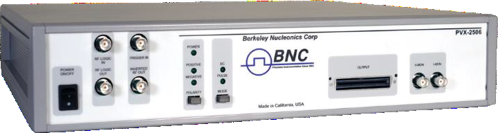
1. General Description
The PVX-2506 pulse generator is designed for pulsed I-V (current-voltage) characterization of semiconductor devices at up to 50 volts and 10 amps. It is also well suited for other applications requiring high-current, precision voltage pulses. Because the I-V characteristics of semiconductor devices depend on frequency and temperature, conventional DC test systems let the device reach thermal and semiconductor-trap equilibrium, yielding characteristics different from actual RF operation. By pulsing the device and measuring during the pulse, the PVX-2506 captures measurements before the device heats up, more closely approximating high-frequency operation and avoiding activation of the semiconductor traps.
The PVX-2506 uses a bi-directional MOSFET output stage built on DEI’s DE-Series Fast Power MOSFETs, providing fast rise and fall times with minimal overshoot, undershoot, and ringing, and fast settling. The device under test (DUT) stabilizes within a few hundred nanoseconds. A quiescent (bias) voltage can hold the DUT at a voltage other than zero, then pulse above or below it. The unit requires an input gate signal plus pulse (VHIGH) and optional quiescent (VLOW) DC supply inputs; output width and frequency follow the gate, and amplitude follows the VHIGH/VLOW amplitudes. Front-panel controls allow pulsed or DC mode, and integral voltage and current probes facilitate data acquisition. The output is launched on a low-impedance cable that maintains pulse fidelity.
2. Specifications
| Pulse (VHIGH) & quiescent (VLOW) inputs | 0 to 75 VDC, floating; screw terminals, rear panel |
|---|---|
| Output | 0 to 50 V at up to 10 A; controlled by pulse input voltage; 8-pin high-current DSUB connector |
| Pulse rise time | <200 ns at 50 V (10%–90%) |
| Typical settling time | <400 ns, including rise time (10% to 99% point) |
| Pulse width | <1 µs to 100 µs, controlled by input gate |
| Pulse recurrence frequency | Single-shot to 50 kHz, controlled by input gate |
| Maximum duty cycle | 0.50 (50%) |
| Voltage monitor | 1 V/V into 1 MΩ, accuracy <±3%; BNC, front panel |
| Current monitor | 0.1 V/A into 1 MΩ, accuracy <±3%; BNC, front panel |
| Control pulse input | External, +5 V ±1 V into 50 Ω, rise time <20 ns; BNC, front panel |
| General | 19″ rack-mountable, 3½″ × 17″ × 16″; support power 100–240 VAC, 50/60 Hz |
3. Safety
The PVX-2506 is designed to operate from a source that will not apply more than 240 V between the supply conductors or between either conductor and ground; a protective ground through the AC power cord is essential. To avoid shock, plug the unit into a properly wired receptacle before making any connections, and use only a power cord in good condition. Do not remove the covers or operate with them removed — they contain no safety interlock. Do not remove the input or output cables during operation. Any pulsed-power system can trigger randomly on transients, so whenever the unit is on, assume a pulse can appear on the output.
4. Operating Considerations
Theory of operation. The switching elements are power MOSFETs; current is sensed with 0.2 Ω resistors and voltage is sensed directly, buffered, and terminated with a 50 Ω resistor. Control logic derives the floating gate signals from the TRIGGER IN, POLARITY, and DC/PULSE signals. The VHIGH and VLOW inputs must always be positive (because of the polarized storage capacitors), and VHIGH must always be greater than or equal to VLOW in magnitude (because of the intrinsic MOSFET diodes).
Front panel. The LINE switch controls AC power and the POWER LED indicates it is on. TRIGGER IN (BNC, 50 Ω) accepts the 5 V control pulse. The POLARITY switch selects positive or negative pulsing; the MODE switch selects DC or PULSE operation, with POLARITY and MODE LEDs showing switch state. VOLTAGE MONITOR (1 V/V) and CURRENT MONITOR (0.1 V/A) BNCs drive a 1 MΩ oscilloscope input. An RF Logic input/output provides TTL replicas for synchronization, and the OUTPUT is a Molex edge connector.
Rear panel & output. Screw terminals provide +, −, and ground connections for the VHIGH and VLOW supplies (which must be floating); the IEC line-input connector houses the fuses and line-voltage selector. Operate the output into a properly terminated load drawing up to 10 A, keep external connections tight and short, and ensure adequate voltage/power ratings. Keep interconnect cables to 2 feet or less. The control pulse input requires +5 V ±1 V into 50 Ω with a rise time <20 ns — set the amplitude using a 50 Ω load before connecting. The maximum VHIGH/VLOW is 75 VDC; do not exceed it.
5. Preparation for Use
After unpacking, inspect the unit for exterior mechanical damage and inspect the power cord and input module for damage; notify the carrier if the unit is damaged. Standard units ship ready for a nominal 120 VAC input; the three-prong plug grounds the unit automatically through a compatible grounded receptacle — do not operate without a grounded AC input.
Power-up check. With the VHIGH and VLOW supplies off and all controls at zero, set MODE to PULSE and POLARITY to POS (respective LEDs lit). Set the pulse generator to deliver a +5 V (±1 V) pulse into 50 Ω at ~500 Hz with a 10 µs width. Turn on AC power (the LINE indicator lights), connect VHIGH to its terminal strip and the pulse generator to TRIGGER IN, leave the output open-circuit, connect VLOW, and monitor the output via the VOLTAGE MONITOR BNC into a 1 MΩ scope input. Turn on VHIGH and slowly raise it to 10 VDC — the unit should produce a ~10 V output pulse following the incoming trigger.
6. Operating Instructions
Power-up. After completing the power-up check, monitor the output on an oscilloscope using the built-in voltage and current sensors and set the output amplitude by adjusting the pulse-voltage supply. Set the output pulse width and recurrence frequency with the input pulse generator; the output follows the input trigger but does not replicate its exact duration because of asymmetric propagation delays. Power-down: set the pulse-voltage supply to zero and turn it off, then disconnect AC power.
7. Troubleshooting
| Symptom | Possible solutions |
|---|---|
| LINE LED does not illuminate | AC power not plugged in; fuse(s) blown (see fuse replacement). |
| No output pulse | No input trigger; MODE switch in DC position; trigger voltage too low; trigger pulse width too short; trigger frequency too high (reduce); no input pulse voltage (check supply and connections); output not connected correctly; driver damaged (contact BNC). |
Fuses. Use only the fuse values indicated on the rear-panel silkscreen; replacement should be performed by qualified personnel with the AC power cord disconnected. The DE-Series MOSFETs are board-mounted; if they need replacement, return the unit to the factory.
8. System Failure Modes
Over-current failure. When the output is shorted, the PVX-2506 can deliver in excess of 10 A (depending on cabling and supply settings), which exceeds its specifications. Operating above rated current for an extended period may damage the unit, load, and/or cabling. Over-voltage failure: input voltages above 75 V may damage the unit — it is the user’s responsibility to ensure this maximum is never exceeded.
9. Warranty
Warranty is 1 Year standard, unless otherwise specified. Materials and workmanship, return to manufacturer included. The warranty does not apply to any product repaired or altered by unauthorized persons, subjected to misuse, negligence, or accident, or used other than in accordance with furnished instructions. Returns must be preauthorized and accompanied by a return-authorization number.
Factory service and support. Berkeley Nucleonics Corporation, 2955 Kerner Blvd. Suite D, San Rafael, CA 94901. Phone: (415) 453-9955. Email: info@berkeleynucleonics.com. Web: www.berkeleynucleonics.com.
Cited in peer-reviewed research
Independent publications citing this instrument, indexed by Bioz. Citation counts and Bioz Stars ratings are shown live and update as new papers are indexed.