 Powered by Bioz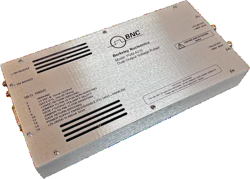
1. Overview
The PVM-4210 is a compact, OEM-style pulse generator module providing two simultaneous differential voltage pulses of up to ±950 V (1900 V differential), with rise and fall times ≥25 ns and pulse widths continuously adjustable from <50 ns to DC. It operates on +24 VDC to +28 VDC support power and features integrated DC high-voltage power supplies.
The module is optimized for differential drive of deflection plates for electrostatic modulation of particle beams in time-of-flight mass spectrometers and accelerators. It will also drive any high-impedance capacitive load such as Pockels cells, Q-switches, electrodes, microchannel plates, acoustic transducers, image intensifiers, and photomultiplier tubes.
Two output channels share common control logic; when the logic receives a gate signal, both channels pulse simultaneously — one from ground to the positive high voltage and the other from ground to the negative high voltage — providing a 1900 V differential pulse. Outputs may also be inverted to pulse from the high-voltage potential to ground. Output pulse width and frequency follow the TTL input gate, and each channel’s amplitude is independently adjustable from 0 to 950 V using screwdriver-adjustable potentiometers on the end panel. Each channel is a half-bridge (totem-pole) design with fast edges and virtually no overshoot, undershoot, or ringing, and includes over-current detection and shut-down circuitry.
2. Safety
The pulser should be serviced only by personnel experienced in high-voltage pulsed-power systems. Do not handle the load or terminations, or remove the input or output cables, while the driver is in operation; ensure the high-voltage supplies have fully discharged before handling the load. The pulser contains reference planes elevated to the potential of the output pulse. Pulsed-power systems can trigger randomly on transients — whenever the driver is on, or high voltage is present, assume a pulse can appear on the output cable.
3. Specifications
Specifications apply to both output channels, measured into a 50 pF load connected to each output with 12″ (~30 cm) of Belden 8218 (75 Ω) coaxial cable.
| Output voltage | 0 to +950 V ±5 V (Channel 1); 0 to −950 V ±5 V (Channel 2) |
|---|---|
| Output voltage adjustment | Screwdriver-adjustable potentiometers, end panel |
| Pulse width | <50 ns to DC (FWHM), controlled by input gate |
| Pulse rise & fall time | ≥25 ns (10%–90%) |
| Pulse recurrence frequency | Single-shot to >20 kHz continuous, 5 MHz burst, controlled by input gate |
| Pulse droop / over-undershoot | <1% droop; <5% over/undershoot |
| Jitter / throughput delay | <1 ns shot-to-shot; 93 ns typical gate-to-output delay |
| Maximum duty cycle / power | Continuous; 4 W maximum average power per channel |
| Output connectors | SHV, end panel; 12″ Belden 8218 75 Ω coaxial output cables |
| Gate | External, TTL into 50 Ω, rise time <20 ns; DSUB connector, end panel |
| Support power | 24 VDC to 28 VDC at 600 mA maximum |
| Dimensions / weight | 5.5″W × 11″L × 1.75″H (140 × 279.5 × 44.5 mm); ~41 oz (1.16 kg) |
Power dissipated per channel driving a capacitive load is approximated by CV²F (internal capacitance 125 pF; Belden 8218 ≈ 21.5 pF/ft). Given the 4 W (4 mA) per-channel supply capability, this formula approximates the maximum load capacitance, frequency, and/or voltage. It does not apply to resistive or inductive loads — contact BNC for assistance with other load characteristics.
4. Connector Pinouts
The DB-15 (P1) provides input and control connections; the positive and negative pulse outputs are SHV connectors on the end panel, with high-voltage adjust potentiometers (full counter-clockwise = 0 V).
| Pin | Function |
|---|---|
| P1-2 | Ground |
| P1-3 | +5 VDC output for the enable circuit |
| P1-6 | Gate (TTL into 50 Ω) |
| P1-7 | +24 VDC return (ground) |
| P1-9 | Non-inverted gate polarity select (jumper to pin 10) |
| P1-10 | Gate/output polarity select |
| P1-11 | Inverted gate polarity select (jumper to pin 10) |
| P1-12 | Gate return (ground) |
| P1-14 | Power-supply enable input (TTL high = enabled) |
| P1-15 | +24 VDC to +28 VDC (600 mA max) |
5. Polarity & Power-Supply Enable
Polarity reversal. Output polarity is selected with jumpers on DB-15 pins 9, 10, and 11. Jumper pins 9 and 10 for a non-inverted output (held at ground when the gate is low, pulsed to the high-voltage potential when the gate is high). Jumper pins 10 and 11 to reverse the polarity (held at high voltage when the gate is low, pulsed to ground when the gate is high).
Power-supply enable. To enable the DC supplies (and generate an output pulse), pin 14 must be held HIGH — either by applying a TTL high signal (input impedance 5 kΩ) or by connecting the +5 V output on pin 3 to pin 14 through a switch. The 5 V output on pin 3 should be used only to satisfy the enable requirement, not as a general-purpose 5 V source.
6. Operating Instructions
Output cabling & load interconnection. The PVM-4210 drives capacitive loads with fast rise times; lower capacitance gives faster rise time. Use only 75 Ω coaxial cable (RG-59 or equivalent), as short as possible, connected directly to the load to minimize inductance and impedance mismatches. If wire leads are unavoidable, keep them short and twist them together to reduce inductance.
Power-up. Before connecting the input TTL pulse generator, set it to deliver a TTL-level pulse into 50 Ω with a repetition rate <20 kHz and a pulse width greater than 45 ns. Connect the DB-15 input and the output to an appropriate load before applying +24 VDC. Monitor the voltage across the load with a high-voltage probe or attenuator, apply +24 VDC to +28 VDC power, and apply a TTL power-supply enable signal (or close the pin 3–pin 14 switch). The module produces positive and negative output pulses equal to the supply voltages, following the incoming gate. Adjust each channel’s output with its potentiometer (set unused channels to zero). If there is no output, disable the high voltage, leave the module on +24 VDC with all connectors in place for about one minute to bleed off stored energy, then disconnect power and refer to troubleshooting.
7. Troubleshooting
| Symptom | Possible solutions |
|---|---|
| No output pulse | No input trigger; trigger voltage too low; trigger pulse width too short (increase); trigger frequency too high (reduce); no input high voltage (check HV supplies); enable circuit not satisfied (ensure +5 VDC on pin 14); no gate polarity selected (jumper pins 9 & 10 or 10 & 11); output not connected correctly; pulser damaged (contact BNC). |
8. Warranty & Service
Warranty is 1 Year standard, unless otherwise specified. Materials and workmanship, return to manufacturer included. BNC will repair or replace, at its option, any product shown to be defective within the warranty period. Equipment claimed to be defective must be returned, transportation prepaid, with a preauthorized return authorization. This warranty does not apply to any product repaired or altered by unauthorized persons, subjected to misuse or neglect, or used other than as authorized in the furnished instructions.
Factory service and support. Berkeley Nucleonics Corporation, 2955 Kerner Blvd. Suite D, San Rafael, CA 94901. Phone: (415) 453-9955. Email: info@berkeleynucleonics.com. Web: www.berkeleynucleonics.com.
Cited in peer-reviewed research
Independent publications citing this instrument, indexed by Bioz. Citation counts and Bioz Stars ratings are shown live and update as new papers are indexed.