 Powered by Bioz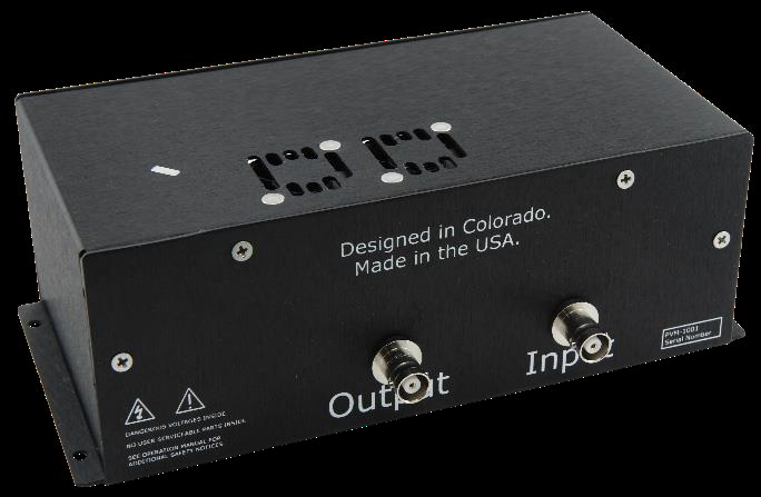
1. Description
The PVM-1001 can achieve zero to 950 V in less than 10 ns rise time, or zero to −950 V in less than 10 ns fall time. This adjustable pulsed voltage source provides pulse widths from 55 ns to 10,000 ns with a standard frequency range up to 1 MHz, and can also provide a 5 MHz burst. The module is designed for a 50-ohm resistive load; typical applications include instrument calibration, component testing, beam steering, and gating photomultiplier tubes (PMTs) and microchannel plates (MCPs).
The output pulse width and frequency are controlled by an external trigger source. Two models are available — one for positive and one for negative output — and the module requires an external positive or negative high-voltage supply of matching polarity. The rear panel has MHV connectors for high-voltage input and pulsed high-voltage output; the front panel has an SMB connector for triggering and a 12 VDC support-power input.
Box contents include the serialized PVM-1001 unit, this operating manual, and a 12 V AC/DC wall-mount adapter with an interchangeable plug. The PVA-1001 input and output cable set is available as an accessory.
2. Safety
Always refer to the Safe Operating Area (SOA) graphs. Do not open the cover — there are no user-serviceable parts inside and opening it exposes you to shock and voids the warranty. Do not install, handle, or remove the output cables or load while the module is operating, and allow at least 10 minutes after power-down before handling the output cable. Allow sufficient space for air circulation, and do not use where liquids are present or in corrosive environments; clean by wiping with a dry or damp cloth.
3. Front & Rear Panel Features
| Support power input (front) | 12 VDC input using the adapter provided with the module. |
|---|---|
| Trigger input (front) | SMB connector with 50 Ω termination for the external trigger input. |
| Air vents & cooling fans | Keep the vents and the top of the module clear for cooling. |
| High-voltage input (rear) | MHV connector — positive or negative depending on the model purchased. Do not plug the incorrect polarity into the module. |
| Output connection (rear) | Pulsed voltage output via an MHV connector. Do not touch any part of the input or output cables while the module is powered up. |
4. Operating Considerations
High-voltage input. The PVM-1001 is rated at a maximum input voltage of 1000 VDC — do not exceed it. The polarity of the DC supply must match the module (a positive-polarity module requires a positive supply; a negative-polarity module requires a negative supply).
Output cabling. The module is designed to operate into 50-ohm loads; an unterminated or improperly terminated output causes excessive aberrations and can damage the pulser. Use the shortest cable possible, use terminators or impedance-matching devices to avoid reflections, ensure all cables and hardware are adequately rated, and never short the output to ground. The unit was tested with a 50-ohm load via 3 feet of RG-58 coaxial cable.
Pulse voltages & trigger. The pulser is rated at a maximum output of +950 VDC or −950 VDC. An external trigger of +5 V ±1 V into 50 Ω is required to gate the module on; these requirements are met by any high-quality low-voltage pulse generator. The duty-cycle limits shown in the Safe Operating Area graphs are set by the module’s cooling capability.
5. Operation
Connect. Ensure the high-voltage supply is off and set to zero. Before connecting the external pulse generator to the Trigger SMB, refer to the SOA graphs and set the generator to deliver a 5 V pulse into 50 Ω with a pulse width from 55 ns to 10,000 ns and a frequency up to 1 MHz, then plug it into the front-panel Trigger SMB. Verify the high-voltage polarity matches the module and connect the supply to the rear MHV input, connect an appropriate load to the MHV output, and (the module has no power switch) plug the AC-DC adapter into the front DC input.
Turn on. Plug the 12 VDC adapter into AC (100–240 VAC) to power the module. Set the high-voltage supply to the required voltage using the datasheet SOA data, then enable it. Enable the trigger input — the PVM-1001 produces an output pulse with a width and frequency identical to the incoming trigger.
Turn off. Disable the trigger input, set the high-voltage supply to zero and disable it, then unplug the 12 VDC adapter from AC. Do not disconnect any connections for approximately ten minutes, to bleed off stored energy.
6. Troubleshooting
There are no serviceable components inside the PVM-1001. If there is no output pulse, check for: no input trigger (supply one); trigger voltage too low (the module requires 0 to 5 V — increase voltage); trigger pulse width too short (increase, per the datasheet SOA); trigger frequency too high (reduce); no input high voltage (check the HV supply and connections); or output not connected correctly (check all cables and connections).
7. Warranty & Service
Warranty is 1 Year standard, unless otherwise specified. Materials and workmanship, return to manufacturer included. The warranty does not apply to any product repaired or altered by unauthorized persons, subjected to misuse, neglect, or accident, or used other than in accordance with furnished instructions. Returns must be preauthorized and accompanied by a return-authorization number.
Factory service and support. Berkeley Nucleonics Corporation, 2955 Kerner Blvd., San Rafael, CA 94901. Phone: (415) 453-9955. Email: operations@berkeleynucleonics.com. Web: www.berkeleynucleonics.com.
Cited in peer-reviewed research
Independent publications citing this instrument, indexed by Bioz. Citation counts and Bioz Stars ratings are shown live and update as new papers are indexed.