 Powered by Bioz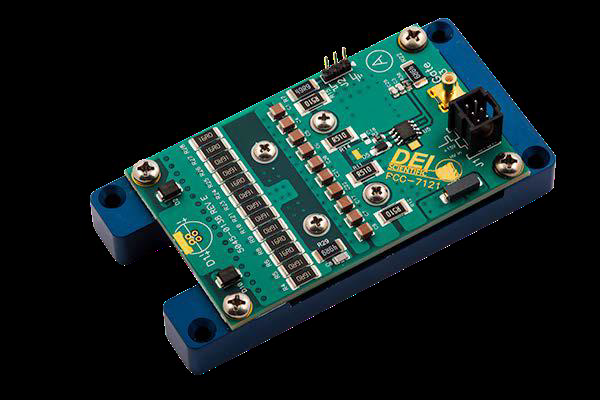
1. Description
The PCO-7121 is a compact and economical OEM pulsed-current laser diode driver module. It is designed to provide extremely fast high-current pulses for driving laser diodes in range finder, LIDAR, atmospheric communications, and other applications requiring high-current nanosecond pulses. The module offers variable output current from 5 A to 50 A with continuously variable pulse widths from 22 ns to 1 µs and frequencies up to 1 MHz.
Mounting pads allow the laser diode to be mounted directly to the driver; the four-hole pattern accepts TO-18, TO-5, TO-52, 5.6 mm, and 9 mm packages. Two solder pads at the end of the board accept various laser diode packages mounted on-axis, or a low-inductance stripline cable can connect the board to a remotely located diode. The DC high voltage and +15 VDC power supplies connect via J1 (a six-pin header) using the supplied control cable; pulse current depends on the HV supply voltage over 0 V to +95 V (maximum). Externally generated gate pulses are fed via J1 or SMB connector J3, and their width and repetition rate set the timing of the output pulses. A current monitor output allows the diode current to be observed in real time on an oscilloscope.
2. Safety
Do not install, handle, or remove the PCO-7121 while it is operating. Do not use the device in a manner not specified by the manufacturer. Allow sufficient space for air circulation, and do not use where liquids are present or in corrosive environments.
3. Design Considerations
Many stray elements affect performance; the most important is stray inductance, which includes the output current loop’s circuit elements and its physical inductance and strongly affects pulse width and peak output current. The PCO-7121 minimizes the stray inductance of its own components, but the laser diode and its connection also contribute — minimize this by choosing appropriate diode packages and short interconnections.
The driver is supplied mounted on a ½-inch aluminum heat spreader for cooling and mounting; the heat spreader mounting-hole spacing is 92.1 mm × 43.2 mm with 3.8 mm holes. Keep the heat-spreader temperature below 60 °C — provide forced-air cooling or mount to a heat sink or cold plate if it exceeds 60 °C. The module requires 30 minutes to thermally stabilize; after adjusting current, pulse width, and frequency, readjust the current once the module has stabilized.
The gate signal may be input via JP1 pin 2 or SMB connector J3 using 50 Ω coaxial cable (center conductor is the gate, shield is the return); keep all connections as short as possible. The gate should be TTL (+3 V to +5 V) into 50 Ω, with the pulse-generator level set while terminated into 50 Ω before connection. The output current pulse width and frequency follow the input gate. Output current is set by the amplitude of the high-voltage input, which charges the on-board energy-storage capacitors.
4. Connectors & Accessories
| J1 control connector | Pins 1, 3, 5: common return for gate, 15 V, and high voltage; Pin 2: gate input; Pin 4: +15 VDC input; Pin 6: high-voltage input. |
|---|---|
| J2 current monitor | Pin 1: current monitor (+); Pin 3: current monitor (−). |
| Current Monitor Cable (PCA-9140) | Optional — lets you monitor the output current pulses on an oscilloscope; ratio 20:1 (20 A to 1 V). |
| Output Cable (1820-0030) | Optional micro-stripline cable to connect to a remote laser diode with minimum added inductance. |
| Control Cable (6100-0137) | Included with the PCO-7121. |
5. Operation
Setup. Verify the PCO-7121 is off when connecting or disconnecting the laser diode or load, and make the laser connection with the correct polarity. Connect the gate source to J1 pin 2 or SMB J3 (set the external trigger to 50 Ω and keep frequency and pulse width below the maximum on the SOA graphs), the +15 VDC housekeeping supply to J1 pin 4, and the high-voltage supply to J1 pin 6 (do not enable it yet; do not exceed 95 VDC), with all returns to pins 1, 3, and 5. Connect an oscilloscope to the current monitor (J2, 50 Ω termination, ~20 A/V) if desired.
Power up & enable. Verify the external trigger and high voltage are disabled, then power up the +15 VDC source. Set the output current by varying the high-voltage input (do not exceed 95 VDC), enable the high-voltage source, set the external trigger for the desired frequency and pulse width (within the SOA), and enable the trigger. Verify the output with the current monitor, and readjust the current after 30 minutes. Power down: disable the external trigger, disable the high-voltage source, then power down the +15 VDC source.
6. Warranty & Service
Warranty is 1 Year standard, unless otherwise specified. Materials and workmanship, return to manufacturer included. The warranty does not apply to any product repaired or altered by unauthorized persons, subjected to misuse, neglect, or accident, or used other than in accordance with furnished instructions. Returns must be preauthorized and accompanied by a return-authorization number.
Factory service and support. Berkeley Nucleonics Corporation, 2955 Kerner Blvd., San Rafael, CA 94901. Phone: (415) 453-9955. Email: operations@berkeleynucleonics.com. Web: www.berkeleynucleonics.com.
Cited in peer-reviewed research
Independent publications citing this instrument, indexed by Bioz. Citation counts and Bioz Stars ratings are shown live and update as new papers are indexed.