 Powered by Bioz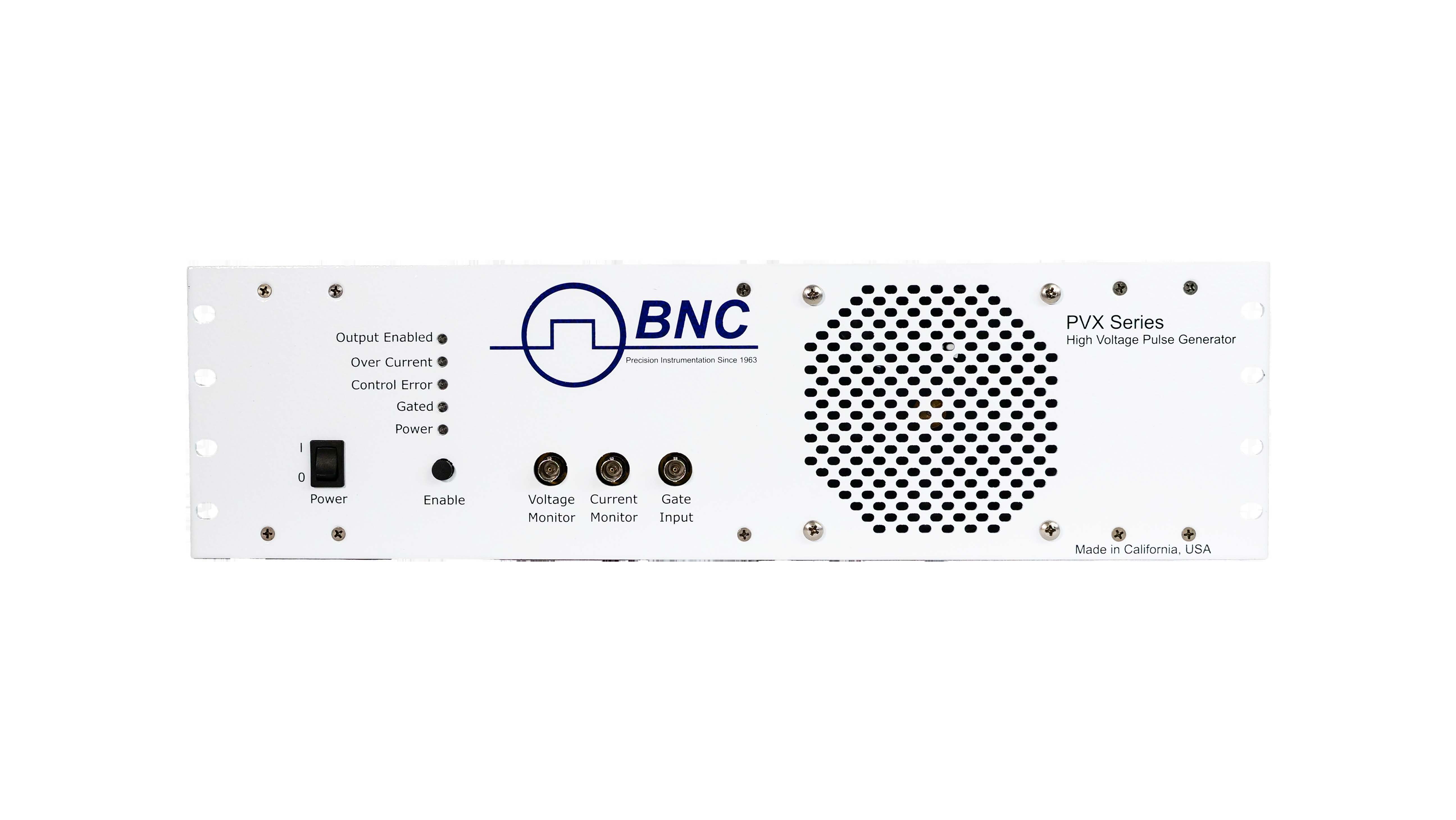
1. General Description
The BNC PVX-4140 is a solid-state high-voltage pulser designed to drive capacitive loads such as grids and deflection, reflection, and acceleration plates. It features an output voltage swing of up to 3500 V, peak current up to 25 A, and continuous current up to 0.1 A, and can output DC as well as very flat voltage pulses into a capacitive load.
The PVX-4140 generates single-ended output pulses from ground to +3500 V or from ground to −3500 V; it can also generate pulses originating from a voltage offset from ground. The offset can range from −3500 V to +3500 V with a maximum differential of 3500 V.
2. Specifications
Refer to the PVX-4140 datasheet on the Berkeley Nucleonics website for the full specifications.
3. Safety
The high-voltage capability of this instrument dictates caution when operating it. The following is a summary of general safety precautions that must be observed during all phases of operation of the PVX-4140.
- Risk of lethal electric shock. Do not touch the output or load while the PVX-4140 is operating. This instrument produces lethal levels of electric current at its output.
- Do not operate this instrument unless another person, capable of rendering first aid or resuscitation, is present.
- Safe and proper operation of this instrument is the responsibility of the user.
- The cover should never be removed. There are no user-serviceable items inside.
- Always turn the high-voltage power supplies and the PVX-4140 off before working with the load or the input and output cables.
- Do not remove the input or output cables while the instrument is in operation, and never short-circuit the output.
- Pulsed-power systems can trigger randomly via transients. Whenever the PVX-4140 is on, or voltage is present in the chassis, assume a pulse can appear on the output connector.
3.1 Power Source
The PVX-4140 is designed to operate from a power source that will not apply more than 240 volts AC between the supply conductors or between either supply conductor and ground. A protective grounding connection by way of the grounding conductor in the AC power cord is essential.
3.2 Grounding
The PVX-4140 is grounded through the grounding conductor of the AC power cord. To avoid electrical shock, plug the PVX-4140 into a properly wired receptacle before making connection to any input or output connectors. Use only a power cord that is in good condition.
3.3 General Operating Precautions
Do not remove the input or output cables while the instrument is in operation. Never short-circuit the output. Failure to observe these precautions can result in potential electric shock to personnel, arcing, and damage to the connectors and the instrument.
4. Operating Considerations
4.1 Output Cabling
The PVX-4140 is designed to drive capacitive loads with fast rise times. Because the output current is limited, increasing the load capacitance lengthens the rise time. The instrument is supplied with a 6-foot length of RG-59 coaxial cable (21.5 pF per foot) and is series-terminated in the characteristic impedance of the cable (75 Ω). BNC recommends using the shortest possible cable for the fastest rise times and best pulse fidelity.
4.2 Load Simulation
The PVX-4140 was tested with a 50 pF capacitive load connected to the output via 6 feet of RG-59 coaxial cable.
4.3 Gate Input
A logic level of +5 V ±1 V into 50 Ω with a rise time <20 ns is required to gate the PVX-4140. Set the amplitude of the gate pulse using a 50 Ω load (for example, a 50 Ω scope input) before connecting it to the PVX-4140. If the gate pulse is greater than +5 V into 50 Ω, pulse stretching can occur.
4.4 High-Voltage Inputs
The absolute maximum rating for the high-voltage inputs is ±3500 V. In addition, the +HV Input must never be more than +3500 V above the −HV Input.
4.5 Output Pulse Considerations
The PVX-4140 can generate single-ended output pulses from ground to +3500 V or from ground to −3500 V, or pulses from a voltage offset (−3500 V to +3500 V), with the +HV Input always equal to or greater than the −HV Input and never more than +3500 V above it. If operated with a single supply for unipolar pulses, the unused high-voltage input must be grounded. When the Gate input is high, the +HV Input is switched to the output; when the Gate input is low, the −HV Input is switched to the output. A negative-going pulse can be generated by logically inverting the Gate input.
4.6 Controls and Indicators
Power Switch & LED. The rear-panel power switch controls all AC power; the front-panel Power LED illuminates when AC power is on.
Enable Button & LED. The Enable button enables and disables the pulse output; the Output Enabled LED illuminates when the output is enabled.
Gate Connector. Logic-level pulses at the Gate input control the output (+5 V into 50 Ω, rise time <20 ns). The output follows the Gate input width and frequency.
Gated LED. Illuminates when a gate signal of appropriate amplitude and width is received. If it is not illuminated, the PVX-4140 will not generate an output pulse.
Over Current LED. Illuminates if the output pulse current exceeds the positive or negative current limit. In Auto Reset mode a fault inhibits the output for 6–7 ms; otherwise reset manually (press Enable twice) or via the remote reset. If it illuminates continuously, correct the fault before operating.
Control Error LED. Not used in this model (to permit burst-mode operation).
Current Monitor. BNC connector providing a 10 A/V scaled version of the output current (scope input 50 Ω).
Voltage Monitor. BNC connector providing a 1 V per 1000 V scaled version of the output pulse voltage (scope input 1 MΩ).
4.7 Remote Control
The PVX-4140 can be operated via remote control. The Remote Interface connector is a DA-15 socket on the rear panel with the pinout below.
| Pin | Function | Description |
|---|---|---|
| 1–5 | GND | Ground |
| 6 | Enable Status | Output: active low, open drain, 24 mA max ON, 24 V DC max OFF |
| 7 | Control Error Status | Output: active low, open drain (not used) |
| 8 | Power Status | Output: active low, open drain, 24 mA max ON, 24 V DC max OFF |
| 9 | Enable | Input: low-to-high transition to enable, disable, or reset |
| 10 | Invert | Input: pull low to invert the Gate input |
| 11 | Remote | Input: pull low for remote operation |
| 12 | Interlock | Input: pull low to satisfy the interlock |
| 13 | Auto Reset | Input: pull low to enable auto reset |
| 14 | Over Current Status | Output: active low, open drain, 24 mA max ON, 24 V DC max OFF |
| 15 | Gated Status | Output: active low, open drain, 24 mA max ON, 24 V DC max OFF |
The inputs are internally pulled high; pull the Remote pin low for remote operation, which disables the front-panel Enable button. The Enable, Interlock, Invert, and Auto Reset inputs are always active regardless of the Remote state. The Interlock input (pin 12) must be connected to Ground (pin 4) to satisfy the interlock as shipped. Status outputs (pins 6, 8, 14, 15) are open drain and require external pull-up resistors (1 kΩ or larger) to a supply of up to +24 V DC.
5. Preparation for Use
5.1 General
After unpacking, perform an initial inspection and preliminary electrical check to ensure the instrument is in good working order. Notify the carrier immediately if damage is found.
5.2 Initial Inspection
- Inspect the instrument for exterior mechanical damage.
- Inspect the input power cord and input power module for damage.
5.3 Electrical Installation
Standard PVX-4140 units ship ready for use with a nominal 110–240 VAC input. The input power cord terminates in a three-prong polarized plug; inserting it into a compatible grounded receptacle automatically grounds the instrument. The instrument must not be operated without a grounded AC input.
5.4 Electrical Check & Power-Up
Before proceeding, review the precautions in Section 3, then power up as follows:
- Insert the supplied DA-15 plug into the rear-panel socket. As configured by the factory, pins 4 and 12 are jumpered to satisfy the interlock and pins 5 and 13 are jumpered to enable auto reset. This plug must be installed for the interlock to be satisfied.
- Set up the gate pulse generator to deliver a +5 V ±1 V pulse into 50 Ω (approximately 500 Hz, 1 µs width).
- Ensure both high-voltage power supplies are off.
- Connect the positive supply to the +HV Input SHV connector and the negative supply to the −HV Input. For positive-only pulses, ground the −HV Input; for negative-only pulses, ground the +HV Input.
- Connect an appropriate load to the rear-panel SHV output connector.
- Display the output on an oscilloscope via a high-voltage probe at the load, or via the front-panel Voltage Monitor (scope input 1 MΩ).
- Plug in the power cord and turn on the rear-panel Power switch; the Power LED should illuminate.
- Connect a coaxial cable from the pulse generator to the Gate input.
- The PVX-4140 powers up in a faulted condition; once enabled, the fault clears within about 5 seconds. Enable the instrument by pressing the Enable button.
- Slowly increase the high-voltage supplies until the desired load voltage is reached. The output follows the width and repetition rate of the Gate input.
- If there is no output or it is severely distorted, turn off the HV supplies, leave connections in place for about 5 minutes to bleed off stored energy, then disconnect AC power and refer to Troubleshooting.
6. Operating Instructions
6.1 Power-Up Procedures
- Monitor the output on an oscilloscope (HV probe at the load, or the front-panel Voltage Monitor). Set the output amplitude by adjusting the high-voltage supplies.
- Set the pulse width and repetition frequency using the Gate input pulse generator. The output follows the Gate input but does not exactly replicate its timing because of system propagation delay.
6.2 Power-Down Procedures
- Set the high-voltage power supplies to zero.
- Turn the high-voltage power supplies off.
- Turn the PVX-4140 power switch off.
- Allow the instrument to bleed off stored energy (about 5 minutes).
- Disconnect AC power from the instrument.
7. Troubleshooting
Before servicing or troubleshooting, review the safety summary in Section 3. The table below summarizes potential problems and solutions; if these do not resolve the issue, contact BNC customer service.
| Symptom | Possible cause |
|---|---|
| Power LED does not illuminate | AC power not plugged in; fuse(s) blown |
| Cannot enable output | External remote interlock circuit not satisfied |
| No output pulse | Output not enabled; interlock not satisfied; no gate input; gate voltage too low; gate width too narrow; gate frequency too high; no high voltage; output not connected correctly; instrument damaged |
7.1 Fuses
To avoid fire hazard or damage to the instrument, use only the fuse types listed on the rear panel. Fuse replacement should be performed by qualified personnel only.
8. System Failure Modes
The PVX-4140 generates large-amplitude current pulses with very fast rise and fall times. There is limited over-current and over-voltage protection; it is the user\u2019s responsibility to ensure the interconnect cables and load do not create transients or over-current/over-voltage conditions that could damage the instrument. Failure to do so voids the warranty.
8.1 Over-Current Failure
Depending on the load voltage, the over-current limit may or may not be exceeded even into a shorted load; typically the output must exceed 733 V. If the output exceeds 733 V into a short, the Over Current LED illuminates. Prolonged operation into a short can damage the instrument, load, and/or cabling. In Auto Reset mode the output is inhibited for 6–7 ms; otherwise reset manually (press Enable twice) or via the remote reset. If the LED illuminates continuously, correct the fault before continuing.
9. Warranty
Warranty is 1 Year standard, unless otherwise specified. Materials and workmanship, return to manufacturer included. This warranty does not apply to any product that has been repaired or altered by unauthorized persons in a way that affects its performance, stability, or reliability; subjected to misuse, neglect, or accident; or connected, installed, adjusted, or used other than in accordance with BNC instructions.
BNC’s sole obligation and the buyer’s sole remedy under this agreement are limited to a refund of the purchase price or, at BNC’s discretion, repair or replacement of defective product returned to the BNC factory, transportation prepaid, within the warranty period. BNC is not liable for consequential or incidental damages. Returns must be preauthorized and accompanied by a BNC return authorization number.
10. Factory Service
If the procedures above fail to resolve an operational problem, contact the factory for assistance.
Phone: (415) 453-9955 · Email: info@berkeleynucleonics.com · Web: www.berkeleynucleonics.com
Berkeley Nucleonics Corporation, 2955 Kerner Blvd., San Rafael, CA 94901
Document Version: rev A · Print Code: 142021230
Cited in peer-reviewed research
Independent publications citing this instrument, indexed by Bioz. Citation counts and Bioz Stars ratings are shown live and update as new papers are indexed.