 Powered by Bioz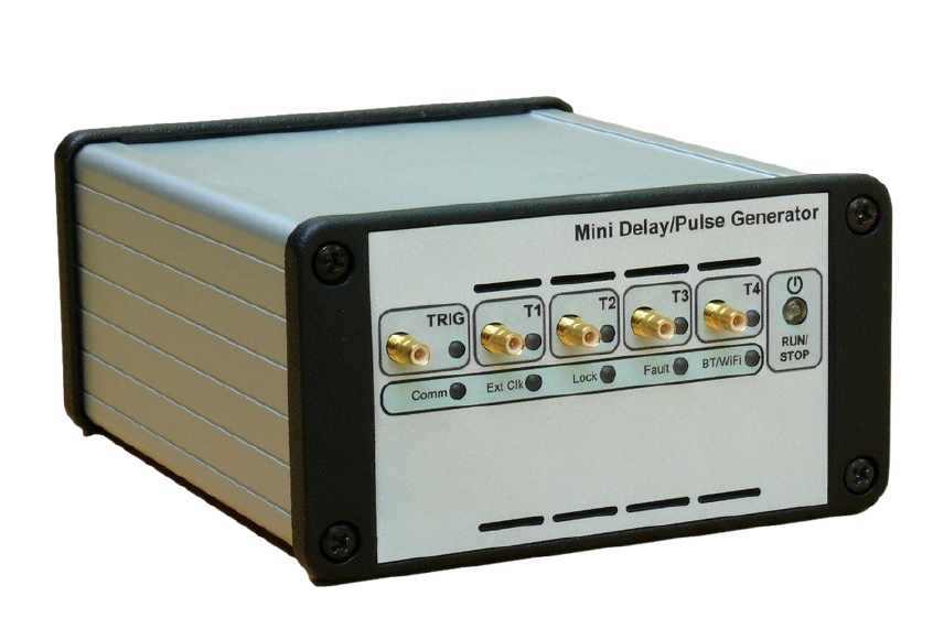
1Overview
The Model 750 provides 4 (or 8, with the channel-extension option) independent delayed pulses. Delays up to 100 seconds can be programmed with 100 ps resolution, with channel-to-channel jitter under 50 ps RMS. An option enhances delay resolution to 1 ps and reduces jitter to under 10 ps RMS.
Each output delivers 1.5 V to 5 V pulses with 1 ns rise/fall time into 50 Ω. Pulse amplitude, polarity, width, and burst count are independently adjustable on every channel.
Two external trigger inputs or three internal synchronized timers (0.01 Hz to 50 MHz) or a software command can trigger any selected channel, in either single-shot or repetitive mode. A Gate input quickly inhibits selected channel outputs, and can also be configured as a second external trigger or as a link for daisy-chaining two Model 750 units together for additional channels.
The Model 750 uses an internal 100 MHz TCXO clock reference, or an external user-programmable clock from 10 MHz to 240 MHz. Front-panel LED indicators show input/output activity, and a RUN/STOP button enables or disables all channel outputs at once. A multi-channel Real-Time Chart View lets you visualize every channel output on a common time chart from a PC, with zoom and cursor tools for precise timing measurement.
2Key Features
- 4 independent delay channels (8 with the channel-extension option)
- 100 ps delay resolution (1 ps with the resolution option)
- 50 ps channel-to-channel RMS jitter
- 1.5 V to 5 V output into 50 Ω, 1 ns rise/fall, independently adjustable width, polarity, amplitude, burst, and MUX mode per channel
- Up to 50 MHz independent trigger rate (single-shot or repetitive) per channel
- External trigger mode with prescaler, or internal trigger from three synchronous programmable timers, or software command
- Gate input, selectable as a second trigger or as a daisy-chain link between two units
- External clocking up to 240 MHz, user programmable
- USB and Ethernet control, with a browser-based control panel — no software install required
- Ultra-compact, low-power packaging
3Applications
- System laser timing control
- ATE applications
- Laser pulse picking
- Precision pulse applications
- Instrument triggering
- Component test
A common application synchronizes every device in a picosecond laser system from one compact unit and one interface: the Model 750's clock reference input receives a signal from the laser oscillator (via an optical-to-electrical converter). Each amplifier in the chain — pump laser, Q-switch, Pockels cell — or diagnostic instrument — digitizer, calorimeter, camera — then receives repetitive or single pulses, independently adjusted in rate, delay, amplitude, polarity, and width, synchronized to that reference with very low jitter. Four GPIO lines under software control add security or low-frequency device interlocks to the same setup.
4Front & Rear Panel
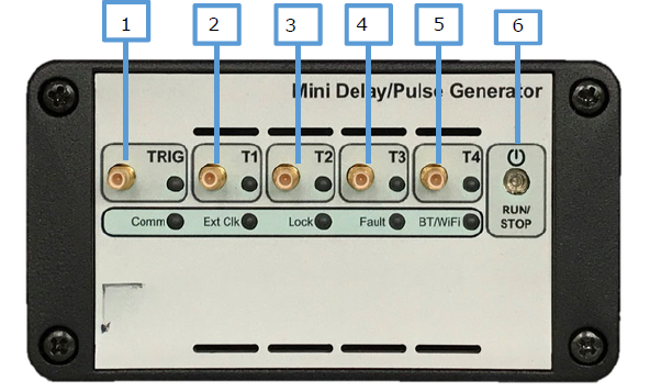
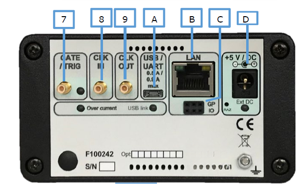
| Front Panel | Rear Panel | ||
|---|---|---|---|
| 1 | Trigger input: SMB connector | 7 | Gate input: SMB connector |
| 2 | T1 channel output: SMB connector | 8 | Clock input: SMB connector |
| 3 | T2 channel output: SMB connector | 9 | Clock output: SMB connector |
| 4 | T3 channel output: SMB connector | A | USB connection: micro-AB connector |
| 5 | T4 channel output: SMB connector | B | LAN connection: RJ45 connector |
| 6 | Power ON/OFF, or RUN/STOP for channel outputs | C | GPIO: SHM-103 Samtec connector |
| D | +5 V DC power plug: 2.10 mm jack | ||
5Pulse Shaping Modules
Optional accessory modules condition the Model 750's SMB outputs for specific application needs.
| Function | Description |
|---|---|
| Electrical-to-optical pulse converter | 1 ns rise time |
| Optical-to-electrical converter | Paired with the electrical-to-optical converter, transmits a fast pulse over up to 1 km |
| Sub-nanosecond pulse stretcher | From a pickup diode, to provide the Model 750's clock reference |
| Line driver | 1 to 4 lines, 50 Ω, up to 150 MHz rate |
| HV pulse generator | 15–70 V, <2 ns rise time into 50 Ω |
| TTL line driver | 4 channels, 50 Ω, up to 150 MHz rate |
6Specifications
| Delay Channels | |
|---|---|
| Number | 4 independent (8 with channel-extension option) |
| Range | 100 seconds |
| Resolution | 100 ps (1 ps with resolution option) |
| RMS jitter | <50 ps + delay × 10-7, channel to channel <1 ns, external trigger to any channel <50 ps, external clock to any channel (10 ps with resolution option) |
| Accuracy | <250 ps + delay × 10-6 (<100 ps + delay × 10-6 with resolution option) |
| Time base | Internal 200 MHz, ±1 ppm stability |
| External Trigger Mode | |
|---|---|
| Input "TRIG" | Single or repetitive rate up to 40 MHz, programmable prescaler, adjustable threshold +100 mV to +5 V (1 mV step), adjustable positive/negative slope, 5 ns min pulse width |
| Trigger delay | <85 ns insertion delay |
| Internal Trigger Mode | |
|---|---|
| Rate, repetitive | Three timers, 0.01 Hz to 50 MHz (5 ns steps) |
| Rate, single | Synchronized on internal timers or software command |
| Channel Output Pulse (T1–T4, and T5–T8 with option) | |
|---|---|
| Amplitude | 1.5 V to 5 V, 1 mV steps, into 50 Ω (3.0 V to 10 V, 2 mV steps, into high impedance >1 kΩ) |
| Rise/fall time | 1 ns / 1 ns into 50 Ω; 2 ns / 2 ns into high impedance, at full scale |
| Width | 10 ns to 10 s, 5 ns steps |
| Polarity | Positive or negative |
| Burst mode | 1 to 1,000,000,000 pulses, adjustable period in 5 ns steps |
| MUX mode | Any channel may be ORed to all outputs, per group of 4 |
| Connector | SMB |
| External Clock Reference | |
|---|---|
| Threshold | 0 V, internal 50 Ω |
| Level | Min −10 dBm, typical 6 dBm |
| Frequency | 10 MHz to 240 MHz; user programmable in 0.25 MHz steps up to 120 MHz, then 0.50 MHz steps to 240 MHz |
| Clock Output | |
|---|---|
| Level | >500 mV p-p into 50 Ω, AC coupled |
| Frequency | 100 MHz on internal clock, or matches the external reference when externally clocked |
| Gate / Second Trigger / Daisy Chaining | |
|---|---|
| Function | Gate, or second external trigger with adjustable threshold, or daisy chaining to a second Model 750 |
| Input | Active high or low in gate mode; positive/negative slope, rate <40 MHz, in trigger mode |
| GPIO | |
|---|---|
| Lines | 4 × input or output, 0 or 3 V level, >20 kΩ input impedance, 100 Ω output impedance |
| General | |
|---|---|
| Interface control | USB to UART, Ethernet 10/100 Mb/s |
| User's sets | 8 sets to save/recall specific configurations |
| Software tools | Free drivers for Windows and Linux; browser-based control panel; USB application with GUI included |
| Power consumption | 2.5 W to 15 W depending on configuration |
| Power supply | USB, or external AC (80–264 V / 47–63 Hz) to DC (5 V, 4 A); adapter included |
| Size and weight | 108 × 58.6 × 129 mm, <1 kg |
7Options & Ordering
| Option | Description |
|---|---|
| Channel extension | Extends the base 4-channel unit to 8 channels |
| 1 ps resolution | 1 ps delay resolution (4-channel model only), with channel-to-channel jitter <10 ps at short delay and 50 ns minimum width; narrow-pulse mode allows 3 ns minimum width in 1 ps steps on two channel outputs |
| 5″ SMB-to-BNC cable | Adapter cable accessory |
| Model | Description |
|---|---|
| Model 750-4C | 4-channel mini pulse & delay generator (base version) |
| Model 750-8C | 8-channel mini pulse & delay generator (with the channel-extension option) |
To request a quote or discuss a configuration, contact Berkeley Nucleonics Corporation at info@berkeleynucleonics.com or 800-234-7858.
8Operating Principles
A time-base function supplies a 200 MHz internal reference, or accepts an external 10–240 MHz reference; the internal time base is also available on the rear-panel clock output. A trigger controller provides two modes. In external trigger mode, a rising edge on the front-panel TRIG input triggers all delay channels, with each channel's rate set to single-shot, repetitive, or inhibited; a prescaler divides the trigger input frequency by an integer from 1 to 1,000,000,000. In internal trigger mode, delay channels are triggered from three frequency-programmable timers, with each channel's rate again set to single-shot, repetitive, or inhibited.
The Gate input quickly inhibits all selected channel outputs, and can alternately be configured as a second external trigger or as an input/output for daisy-chaining two Model 750 units to increase the total channel count. A RUN/STOP button (also the power switch) enables or disables the output for all channels at once.
| Trigger source | Trigger In | Gate In | Timer 1 | Timer 2 | Timer 3 | Command | Inhibited |
|---|---|---|---|---|---|---|---|
| External mode | X | X | |||||
| Internal mode | X | X | X | X | X |
Each output pulse can be independently adjusted in level, width, and polarity, and may be ORed with other outputs in its group of four. Outputs are designed to drive a 50 Ω load; on a high-impedance load, output level doubles. A burst mode adjusts the number of pulses per trigger via burst count and burst period. A narrow-pulse mode (available with the resolution option) uses a pair of delay channels — one to start the output pulse, one to stop it — for precisely adjustable pulse widths down to 500 ps.
The unit can run stand-alone, without a PC: an Auto-Run option starts output pulses automatically at power-up, and all parameter values are stored in non-volatile memory across 8 selectable user sets.
9Example of Channel Outputs Mode
Mode Repetitive and Single
Mode Burst and Mux
Pulse Picking (synchronized on Timer N°3)
10Control & Software
Two ways to control the Model 750: an easy remote path over Ethernet through an embedded web server, with no software install required, and a general remote path over Ethernet or USB using the included control software or your own application.
Easy Remote (Web Control Panel)
Via Ethernet and the control panel's web pages, with no specific software application required. The page, served by the unit's embedded web server, provides an easy way to configure every setting.
- A main menu displays and controls the trigger and clock system (level, slope, prescaler, clock input/output, trigger generators), per-channel delay/width/amplitude/polarity settings, extended settings (burst mode, gate, MUX mode), a RUN button enabling output on all channels, and a Trigger button for a single trigger synchronized to the selected source
- A parameters menu changes the IP address and other unit-level settings
- A GPIO menu configures the four input/output lines
- A Chart View opens a window showing every channel's output on a common time chart in real time, with zoom and cursor tools for detailed timing inspection
The instrument stores its own configuration, so the control panel simply reflects it. The page opens in any standard browser (Chrome, Firefox, or Edge): connect the Model 750's Ethernet port to your network, enter the unit's IP address (see the User's Manual) into your browser, and the control panel loads automatically.
General Remote (Ethernet/USB)
Via Ethernet or USB and a software application (see examples in the User's Manual). A USB application with a GUI similar to the web control panel is included, alongside an ASCII command set over USB (virtual COM port) or Ethernet (TCP port 4000) covering clock configuration, trigger and gate setup, per-channel delay/amplitude/width/polarity/burst/MUX, GPIO, status queries, user-set save/recall, and network configuration. Free Windows and Linux drivers are included.
Cited in peer-reviewed research
Independent publications citing this instrument, indexed by Bioz. Citation counts and Bioz Stars ratings are shown live and update as new papers are indexed.