 Powered by Bioz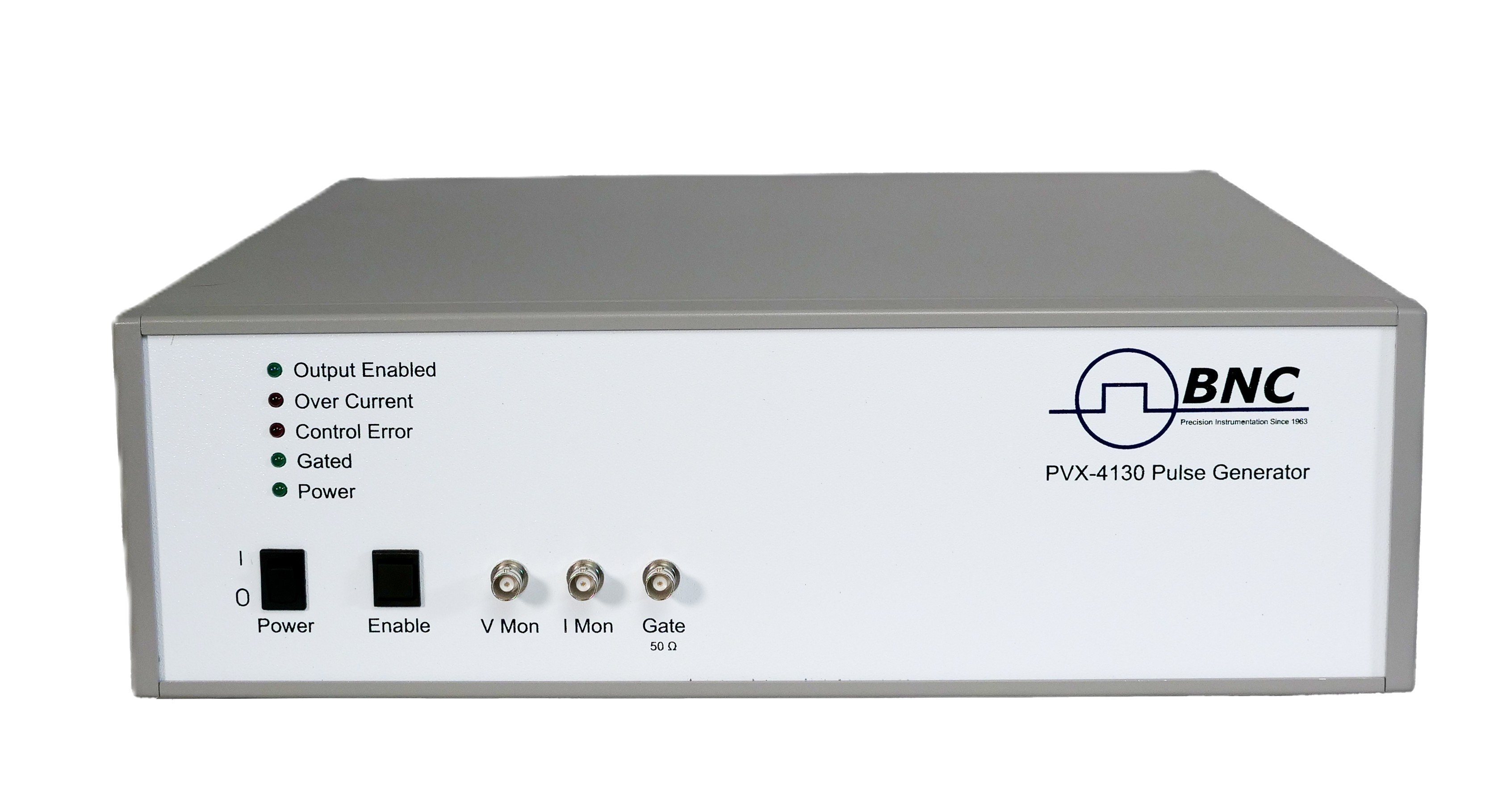
1. General Description
The DEI PVX-4130 pulser is a high-voltage solid-state pulser designed to drive capacitive loads such as acceleration grids and deflection plates. It generates an output voltage swing of 6000 volts, with an output current of 30 amperes peak and 0.1 amperes continuous, producing very flat voltage pulses to DC into a capacitive load.
The PVX-4130 can generate single-ended output pulses from ground to +6000 V or from ground to −6000 V, and can also generate pulses originating from a voltage offset from ground. This offset can be from −6000 V to +6000 V, with a maximum power-supply voltage differential (Vhigh − Vlow) ≤ 6000 V.
2. Specifications
All specifications are measured into a 50 pF load connected with 4 feet (~1.2 m) of RG-58 (50 Ω) coaxial cable, at 6000 V output.
| Output pulse voltage | ±6000 V (Vhigh − Vlow); minimum 0 V. Controlled by power-supply input voltages. |
|---|---|
| Output current | 30 A peak, 0.1 A continuous |
| Pulse rise & fall time | <60 ns (10%–90%) |
| Pulse width | <150 ns to DC, controlled by input gate |
| Pulse recurrence frequency | Single-shot to 10 kHz, controlled by input gate |
| Droop | <1% into a capacitive load |
| Maximum duty cycle | Continuous |
| Gate input | +5 V ±1 V into 50 Ω, rise time <20 ns; Type BNC, front panel |
| +V IN (Vhigh) | External, absolute max ±6000 V; Kings 10 kV rear-panel connector; max input power 100 W (Vhigh + Vlow supplies) |
| −V IN (Vlow) | External, absolute max ±6000 V; Kings 10 kV rear-panel connector |
| Output connector | Kings 10 kV, rear panel |
| Voltage monitor (V MON) | 2 kV/V into 1 MΩ |
| Current monitor (I MON) | 10 A/V into 50 Ω |
| AC power | Nominal 110–240 VAC |
The PVX-4130 can drive loads of a few picofarads to several hundred picofarads, limited by its maximum power dissipation. At lower load capacitances and/or voltages below 6000 V it can operate above 10 kHz. Power dissipated when driving a capacitive load is approximated by CV²F, where C is the total load capacitance (load + cable + the 100 pF internal capacitance of the PVX-4130; RG-58 adds ~30 pF/ft), V is the pulse voltage, and F is the pulse repetition frequency. Given the maximum dissipation of 100 W, this formula approximates the maximum load capacitance, frequency, and/or voltage. Contact BNC for resistive or inductive loads.
3. Safety
The high voltage of this device dictates the use of caution when operating or servicing. The following summarizes general precautions that must be observed during all phases of operation and repair.
3.1 Operating Safety Summary
Power source. The PVX-4130 is designed to operate from a source that will not apply more than 240 VAC between the supply conductors or between either supply conductor and ground. A protective grounding connection through the AC power cord is essential.
Grounding. The PVX-4130 is grounded through the grounding conductor of the AC power cord. To avoid electric shock, plug the unit into a properly wired receptacle before making any input or output connections. Use only a power cord in good condition.
Cover removal. To avoid personal injury, do not remove the covers and do not operate the unit with the covers removed. The covers do not contain a safety interlock.
General operating precautions. Do not remove the input or output cables while the pulser is in operation. Never short-circuit the output. Any pulsed-power system can trigger randomly on transients — whenever the unit is on, or dangerous voltage is present in the chassis, assume a pulse can appear on the output connector.
3.2 Servicing Safety Summary
The PVX-4130 contains dangerous voltages and stored energy. BNC strongly recommends that all repairs and adjustments be performed by factory-qualified personnel. Do not perform internal repair or adjustments unless another person capable of rendering first aid and resuscitation is present.
4. Operating Considerations
Output cabling. The PVX-4130 drives capacitive loads with fast rise times; because output current is limited, lower capacitance gives faster rise time. The unit ships with a 4-foot Teflon-insulated RG-58 coaxial cable (30 pF/ft) and is series-terminated in the cable’s 50 Ω characteristic impedance. Use the shortest cable possible for the fastest rise times and best pulse fidelity.
Load simulation. The unit is tested with a 50 pF capacitive load connected to the output with 4 feet of RG-58 coaxial cable.
Trigger input. A trigger of +5 V ±1 V into 50 Ω with a rise time <20 ns is required to gate the PVX-4130 on. Set the trigger amplitude using a 50 Ω load (for example a 50 Ω scope input) before connecting to the trigger input. A trigger greater than +5 V into 50 Ω can cause pulse stretching.
Pulse voltages +V IN and −V IN. The pulser is rated at a maximum output of ±6000 VDC; ensure this is not exceeded. When the input gate is high, Vhigh is connected to the output; when the gate is low, Vlow is connected. A negative-going pulse can be produced by logically inverting the input gate. Vhigh should always be equal to or greater than Vlow, but never more than 6000 V above it. For single-ended operation, ground the unused power-supply input.
5. Controls & Indicators
| POWER switch & LED | Controls all AC power in the chassis; the POWER LED illuminates when AC power is on. |
|---|---|
| OUTPUT switch & LED | Enables/disables the pulse output; the OUTPUT ENABLED LED illuminates when output is enabled. |
| GATE connector | Front-panel BNC input to gate the pulser: +5 V into 50 Ω, rise time <20 ns. Output pulse width and frequency follow the input gate. |
| GATED LED | Illuminates when a gate signal of the appropriate amplitude and width is received. If not lit, the unit will not generate an output pulse. |
| OVER CURRENT LED | Illuminates if output pulse current exceeds 15 A; the output is inhibited for 6–7 ms. If lit continuously, correct the fault before operating. |
| CONTROL ERROR LED | Illuminates if the input gate frequency exceeds 10 kHz; the output is inhibited. Reduce the gate frequency before operating. |
| I MON | Front-panel BNC, 10 A/V monitor of output current; terminate into 50 Ω (e.g. a scope 50 Ω input). |
| V MON | Front-panel BNC, 2 kV/V monitor of output voltage; terminate into 1 MΩ. |
6. Preparation for Use
Initial inspection. After unpacking, inspect the unit for exterior mechanical damage and inspect the power input cord and input power module for obvious signs of damage. If the unit is damaged, notify the carrier immediately.
Electrical installation. Standard units ship ready for use with a nominal 110–240 VAC input. The input power cord terminates in a three-prong polarized plug; inserting it into a compatible grounded receptacle automatically grounds the unit. Do not operate without a grounded AC input.
Power-up check. Before connecting the pulse generator, set it to deliver a +5 V (±1 V) pulse into 50 Ω at roughly 500 Hz with a 1 µs pulse width. Connect the positive supply to +V IN and the negative supply to −V IN (for +6000 V single-ended output, connect −V IN to ground; ground any unused supply input) with both supplies off. Plug in AC power and turn on the front-panel POWER switch — the POWER LED should light. Connect the pulse generator to the GATE BNC, connect the load to the rear output, and monitor the output at V MON. Slowly raise the high-voltage supplies; the unit should produce an output pulse following the incoming trigger.
7. Operating Instructions
Power-up. After completing the power-up procedure, adjust the driver for the application: monitoring the output on an oscilloscope (via the internal voltage monitor or a high-voltage probe at the load), set the output amplitude by adjusting the high-voltage power supplies. Set the output pulse width and recurrence frequency with the input pulse generator; the output follows the input trigger but does not replicate its exact duration because of asymmetric system propagation delays.
Power-down. Set the high-voltage supplies to zero, turn the high-voltage supplies off, turn off the PVX-4130 power switch, then disconnect AC power.
8. Troubleshooting
| Symptom | Possible solutions |
|---|---|
| POWER LED does not illuminate | AC power not plugged in; fuse(s) blown — see fuse replacement below. |
| No output pulse | No input trigger; trigger voltage too low; trigger pulse width too short (increase); trigger frequency too high (reduce); no high voltage (check supplies); output not connected correctly (check cables/connections); pulser damaged (contact BNC). |
Fuses. To avoid fire hazard or damage, use only the fuse type listed on the rear panel. Fuse replacement should be performed by qualified personnel only, with the AC power cord disconnected. The power MOSFETs are board-mounted; if they need replacement, return the unit to the factory.
9. System Failure Modes
The PVX-4130 generates large-amplitude current pulses with very fast rise and fall times, and has limited over-current or over-voltage protection. It is the user’s responsibility to ensure the interconnect cables and load do not create transients, over-current, or over-voltage conditions that could damage the unit — failure to do so voids the warranty.
Over-current failure. When the output is shorted, the PVX-4130 can deliver in excess of 30 A (depending on cabling and supply settings), which exceeds its specifications. The unit offers limited protection against shorts and arcs to ground, but operating into a short for an extended period may damage the unit, load, and/or cabling.
10. Warranty & Service
Warranty is 1 Year standard, unless otherwise specified. Materials and workmanship, return to manufacturer included. BNC will repair or replace, at its option, any product shown to be defective within the warranty period. Equipment claimed to be defective must be returned, transportation prepaid, with a preauthorized return authorization. This warranty does not apply to any product that has been repaired or altered by unauthorized persons, subjected to misuse or neglect, or used other than in accordance with furnished instructions.
Factory service. Berkeley Nucleonics Corporation, 2955 Kerner Blvd., San Rafael, CA 94901. Phone: (415) 453-9955. Email: info@berkeleynucleonics.com. Web: www.berkeleynucleonics.com. Document version 9100-0218 Rev 4.
Cited in peer-reviewed research
Independent publications citing this instrument, indexed by Bioz. Citation counts and Bioz Stars ratings are shown live and update as new papers are indexed.