 Powered by Bioz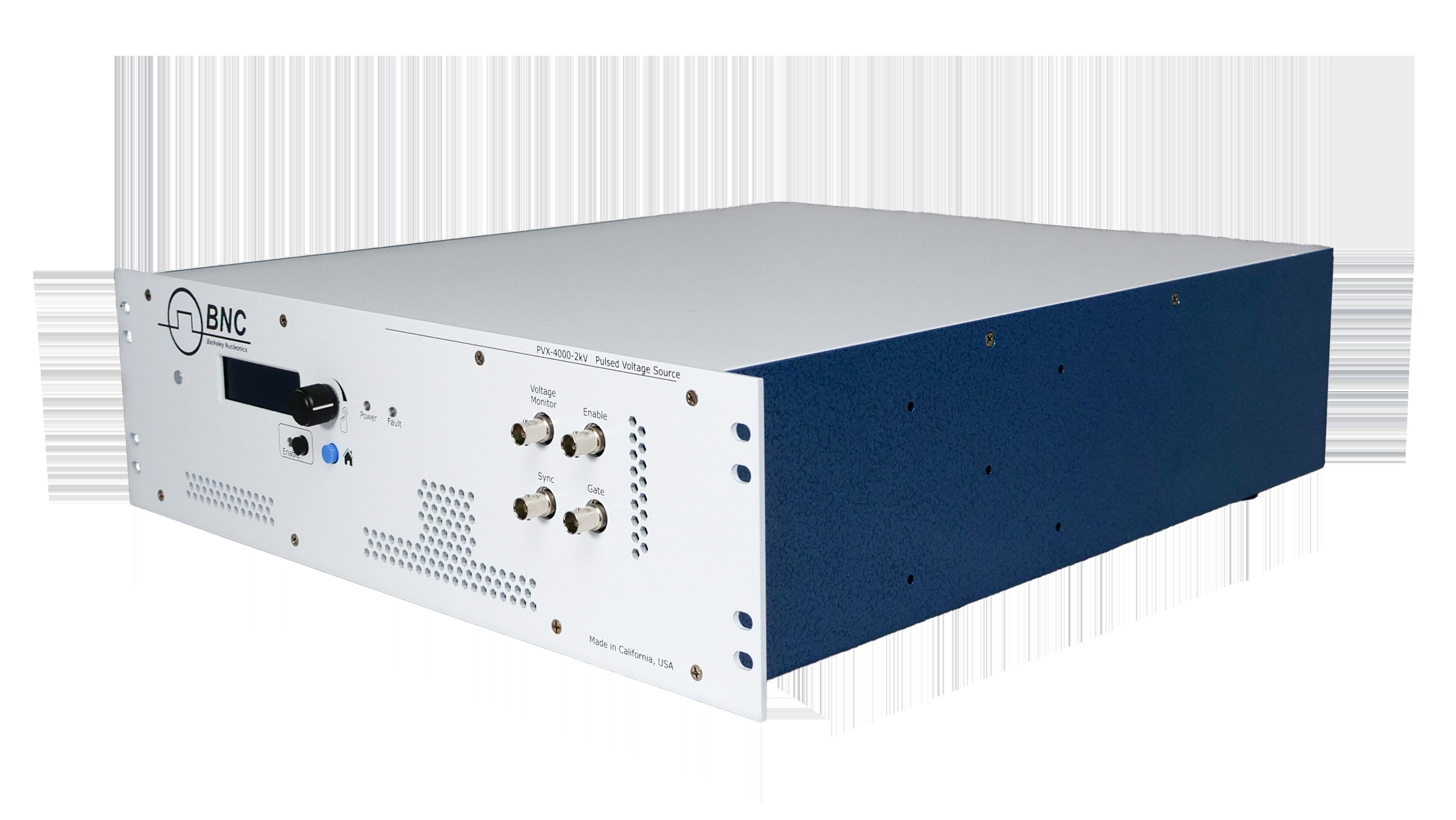
1. Description
The PVX-4000-2kV is an air-cooled pulse generator that produces high-voltage waveforms. Optimized for high-impedance capacitive loads, it is well suited for driving extraction grids and deflection plates for electrostatic modulation of particle beams in time-of-flight mass spectrometers and accelerators. The output voltage can be set to ±2000 V using the internal high-voltage power supplies. The positive and negative outputs must not exceed 2000 V total: Vpositive + |Vnegative| ≤ 2000 V.
The system supports duty cycles from 2% to 98% and repetition rates from 40 Hz to 30,000 Hz using the internal trigger. With the external trigger it operates from single-shot to 100 kHz with a pulse width of 500 ns to 100% duty cycle. Front-panel BNC connectors allow the unit to be externally gated and synchronized (both 50 Ω); the sync output is synchronized to the leading edge of the output pulse and is active with the external trigger.
The PVX-4000-2kV combines a pulse generator and high-voltage DC power supplies into a standalone test system, programmable from the front-panel LCD controls or a computer interface (RS-232 and USB). When the frequency changes, the duty cycle is maintained and the displayed pulse width updates accordingly — change the frequency before the pulse width. Up to five user configurations are stored in nonvolatile memory (location 1 holds the power-up defaults), and analog voltage monitors are provided for observing the load voltage on an oscilloscope.
BNC also offers the PVX-4000-2kV-EX, which runs from an external HV supply instead of the internal one to reach a higher external-trigger repetition rate. It is documented on its own datasheet and manual.
2. Safety
Always refer to the Safe Operating Area (SOA) of the PVX-4000-2kV, located in the datasheet. Do not open the cover — there are no user-serviceable parts inside and opening it exposes you to shock and voids the warranty. Do not install, handle, or remove the output cables or load while the unit is operating, and allow at least 10 minutes after power-down before handling the output cable or load. Allow sufficient space for air circulation, and do not use where liquids are present or in corrosive environments; clean by wiping with a dry or damp cloth.
3. Front Panel Features
| Power LED | Lit when support power is applied to the PVX-4000-2kV. |
|---|---|
| Fault LED | Lit when a fault or error is sensed within the system. |
| Enable LED & button | The output is enabled — and the Enable LED lit — when there are no faults, the Enable BNC connection is made, and the Enable button has been pressed. Press the button to enable or disable the output. |
| Home button | Returns to the main menu once parameters are set. |
| Encoder knob & LCD | The encoder changes the values of displayed parameters; the display shows system information on the home screen. |
| Enable Input (BNC) | Accepts an external dry-contact closure or the factory-supplied shorting BNC plug (PCA-9410). Less than 1000 Ω enables the output; greater than 1 MΩ (open) disables it and creates a fault. |
| Voltage Monitor (VMON) | Monitors the output-cable voltage, scaled 10:1000 (1000 V output = 10 V on VMON). Set oscilloscope termination to 1 MΩ. |
| Gate Input | External-gate BNC, 50 Ω, driven with a 5 V logic level; single-shot to 100 kHz, pulse width 500 ns to DC. |
| Sync Output | 50 Ω BNC providing sync pulses at the leading edge of the output pulse; 0 V for a −HV output pulse, <+3.3 V for a +HV output pulse. |
4. Rear Panel Features
| Output | Winchester Kings 10 kV (1065-2) plug — the output connection for generated voltage pulses. Do not touch the output or cable while the unit is powered up and enabled. |
|---|---|
| Power cord connector | Accepts a NEMA C14 grounding equipment power cord. |
| On/Off power switch | Turns the support power on and off. |
| Communication | USB or RS-232 for automated operation; both use 115,200 baud, 8 data bits, 1 stop bit, no parity, no flow control. Switching from RS-232 to USB needs no power cycle; switching from USB back to RS-232 requires a power cycle. |
Accessories included: a NEMA C14 power cord and a 2-meter pulsed output cable (PCA-9400), which adds 1.57 pF per 1.0 cm of cable to the total load — include this in load calculations.
5. Operating Considerations
Output cabling. The PVX-4000-2kV drives capacitive loads; because output current is limited, smaller load capacitance gives faster rise time. Use the shortest cable possible for the fastest rise times and best pulse fidelity. The unit was tested driving a 360 pF load at 2000 V (a 56 pF capacitor at the end of 2 m of coaxial cable with 1.57 pF/cm).
Pulse voltages. The unit is rated at a maximum output of ±2000 VDC; ensure this is not exceeded. Trigger method. Use either the internal trigger source or an external gate to trigger the output pulse.
6. Local Operation
Local mode is selected automatically at power-up, allowing configuration through the front-panel display and encoder: set the trigger mode (internal or external), frequency, pulse width, and positive/negative high voltage; save or load configurations; enable/disable the output; reset faults; and view port settings and system status.
Setup. Press Enable to disable the output. With the unit off for at least ten minutes, connect the output to the load (verify polarity — typically the center pin is high voltage and the housing is the return), make any External Trigger, Sync, or VMON connections, connect the Enable shorting connector (or a connection under 1000 Ω), and connect AC support power.
Power up. Turn on the rear power switch; the Power LED lights and the Fault LED blinks while the unit boots (~3 seconds). If there are no faults, the Fault LED turns off; a steady Fault LED indicates an error.
Set output voltage. On the Positive HVPS or Negative HVPS screen, press the encoder to edit, rotate to set the value, and press again to change the multiplier (10, 100, or 1000) — keeping Vpositive + |Vnegative| ≤ 2000 V. Set trigger, frequency, and pulse width on their respective screens (internal frequency 40 Hz–30 kHz; pulse width 2%–98% duty). When the frequency changes the duty cycle is maintained, so set frequency before pulse width.
Enable and power down. With no faults and the Enable BNC shorted (<1000 Ω), press Enable (hold up to 2 seconds) — the green LED lights and the unit sends high-voltage pulses. To power down, press Enable to disable, turn off any external trigger, and switch off the rear power. Use the Save/Restore Settings screens to store or recall memory locations 1–5.
7. Remote Operation
A host PC can control the PVX-4000-2kV through its RS-232 and USB interfaces. Any communication on the USB port disables the RS-232 port until the unit is power-cycled (RS-232 is active by default). Serial parameters are 115,200 baud, 8 data bits, no parity, 1 stop bit, no flow control, with the ASCII newline as the end-of-packet character. The command set is based on SCPI; commands and queries must be in all capital letters, with a space before any data. The unit returns a response for every command — wait for it before sending the next. Any change typically needs less than 200 ms.
8. Command List
| Command / Query | Function |
|---|---|
*IDN? | Returns manufacturer, model, serial number, firmware revision, and manufacture date. |
OUTPUT? / OUTPUT:ENABLE / OUTPUT:DISABLE | Returns, enables, or disables the output. |
OUTPUT:TRIGGER? / OUTPUT:TRIGGER:INTERNAL / OUTPUT:TRIGGER:EXTERNAL | Returns or sets the trigger source (internal or external). |
PULSE:WIDTH? / PULSE:WIDTH nn | Returns or sets the output pulse width in nanoseconds. |
PULSE:FREQ? / PULSE:FREQ n | Returns or sets the trigger frequency in Hz (n = 40 to 30000). |
VOLT:POSITIVE? / VOLT:POSITIVE nn | Returns or sets the positive output voltage in volts. |
VOLT:NEGATIVE? / VOLT:NEGATIVE nn | Returns or sets the negative output voltage in volts. |
SAVE:n / RECALL:n | Saves or recalls a configuration; n = 1 to 5. |
FAULT? / FAULT:CLEAR | Returns the fault code (0 if none) or clears faults. |
9. Fault Codes
| Code | Meaning |
|---|---|
| 0 | No fault — system ready to be enabled. |
| 1 | Enable fault — the BNC shorting plug is not present. Make the Enable BNC connection with less than 1000 Ω (shorted), or use the factory-supplied shorting plug. |
| 2 | Temperature fault — the system exceeded its allowed operating temperature. Let it cool and press Home to clear the fault. |
10. Warranty & Service
Warranty is 1 Year standard, unless otherwise specified. Materials and workmanship, return to manufacturer included. The warranty does not apply to any product repaired or altered by unauthorized persons, subjected to misuse, neglect, or accident, or used other than in accordance with furnished instructions. Returns must be preauthorized and accompanied by a return-authorization number.
Factory service and support. Berkeley Nucleonics Corporation, 2955 Kerner Blvd., San Rafael, CA 94901. Phone: (415) 453-9955. Email: operations@berkeleynucleonics.com. Web: www.berkeleynucleonics.com.
Cited in peer-reviewed research
Independent publications citing this instrument, indexed by Bioz. Citation counts and Bioz Stars ratings are shown live and update as new papers are indexed.