 Powered by Bioz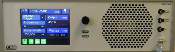
1. Description
The PCX-7500-EX is an air-cooled, high-power current source designed to drive laser diodes, bars, and arrays. The output current can be set from 10 A to 450 A; the compliance voltage is set by an external DC power supply that sources the laser diode's forward voltage, up to 110 V. The pulse width is adjustable from 4 µs to 5,000 µs with a frequency range of 8 Hz to 10,000 Hz.
The PCX-7500 is operated through intuitive front-panel controls; the color QVGA LCD provides immediate visual confirmation of all operating parameters, including current setpoint, internal trigger pulse width and frequency, and error/fault messages. For automated applications, complete control is provided through RS-232, USB, and Ethernet interfaces, and up to four system configurations may be stored in nonvolatile memory. The laser diode connects through a low-impedance stripline cable that preserves pulse fidelity; the output connector is interlocked so the unit is disabled when the connector is removed. Front-panel BNC connectors allow external triggering and synchronization — the trigger input impedance can be set to 50 Ω or 10,000 Ω, and the sync output (delay ~100 ns) tracks the leading edge of the output current pulse.
2. Safety & Safe Operating Area
Always refer to the safe operating section for your model. Do not open the cover — there are no user-serviceable parts inside and opening it exposes you to shock and voids the warranty. Do not install, handle, or remove the output cables or laser diode while the unit is operating, and allow at least 10 minutes after power-down before handling them. Allow space for air circulation (cooling air enters the rear and exits the front), and do not use where liquids are present or in corrosive environments.
3. Front Panel Features
| Touch screen | Graphical interface and touch control for all functions. |
|---|---|
| Encoder knob | Turn to change a value; push to cycle through resolutions. |
| LOCAL button | Returns to front-panel control from computer control; lit when the computer is in control. |
| ENABLE button | Enables or disables the output; lit when enabled. The unit can only be enabled when the keyswitch is ON. |
| Current Monitor (IMon) | BNC to an oscilloscope; 0 V to 1.5 V (≈330 mV at 100 A). |
| External Trigger | BNC accepting external trigger pulses; input impedance 50 Ω or 10,000 Ω. |
| Sync Output | BNC providing sync pulses at the leading edge of the output current pulse. |
| Keyswitch | ON allows the output to be enabled; OFF disables the unit. |
4. Rear Panel Features
| Current Output | Accepts the factory-supplied stripline output cable. Do not touch it while powered up. Absence of a properly installed cable disables the output and creates an output-enable fault. |
|---|---|
| Rear Enable | Accepts a dry-contact closure or the factory-supplied shorting BNC plug; closed contacts or the plug enable the output, open/removed disables it and creates a rear-enable fault. |
| Voltage Monitor (VMon) | BNC scaled to the output voltage, 0 V to ≈1.392 V (0 V to 120 V on the output). |
| USB / Ethernet / RS232 | Communication with an external computer. |
| Power connector & switch | IEC 320 C-19 to NEMA 5-20P grounding power cord; the on/off switch powers the unit. |
Accessories included: AC power cord, output stripline cable (DB-37 male to the unit, DB-37 female at the user end), shorting BNC plug for the Rear Enable, and keyswitch keys. To interface a load, solder the stripline directly or design a two-layer interface board with very low resistance and inductance (wide copper planes, board <0.070″, 2 oz copper or more) to meet the droop and overshoot specifications.
5. Quick Start
Make sure the PCX-7500 is connected with the proper cables and termination, powered up, has all faults cleared, and has the rear enable and keyswitch enabled (icons turn green). From the front panel: press Enable to disable the output; press Output and set the current (10.0–450.0 A) with the encoder resolution ×0.1/×1.0/×10.0, then Done; press Trigger and select Internal or External; set the Frequency (8–10,000 Hz) and Pulse Width (4 µs–5 ms); then press Enable. From a computer: send OUTPUT:DISABLE, TRIG:INTERNAL/TRIG:EXTERNAL, TRIG:INT:FREQ n (8–10000), TRIG:INT:PULSEWIDTH nnnn (4000–5000000 ns), SETPOINT:CURRENT n (10–450 A), then OUTPUT:ENABLE.
6. Operation
Setup & power up. With the unit off for at least ten minutes, connect the laser diode with the correct polarity, make any External Trigger, Sync, Rear Enable, or computer connections, and connect the power cable. Turn on the power switch — the unit boots in about 3 seconds, plays a tune, displays BNC information, and then shows the Home screen (output current, pulse width, frequency, trigger source, forward voltage, and keyswitch/rear-enable/output-connector/temperature status).
Set current, trigger, frequency, and pulse width from the Home screen using the Output, Trigger, Frequency, and Pulse Width icons and the encoder resolutions (current ×0.1/×1.0/×10.0; frequency ×1 to ×5000; pulse width resolution depends on frequency). For external triggering, set the termination (50 Ω or 10 kΩ). The Tools icon opens the Settings menu, where you can view unit information (*IDN?), configure the communication port (RS232 baud rate, USB, or Ethernet DHCP/Static), and save or recall up to four configurations (*SAVE n, *RECALL n). To power down, press Enable to disable, turn the keyswitch OFF, and switch the unit off at the rear.
7. Command Set
The PCX-7500 is controlled via RS-232, USB, or Ethernet. Commands and queries must be in all capital letters, with a space before any data; the end-of-line character is \n, and the unit returns a response for every command — wait for it before sending the next.
| Command / Query | Function |
|---|---|
*IDN? / *LIST? | Returns identity (model, serial, firmware, date) or lists all supported commands. |
*SAVE n / *RECALL n | Saves or recalls a configuration; n = 1 to 4. |
OUTPUT? / OUTPUT:ENABLE / OUTPUT:DISABLE | Returns, enables, or disables the output. |
TRIG? / TRIG:INTERNAL / TRIG:EXTERNAL | Returns or sets the trigger type. |
TRIG:INT:PULSEWIDTH? / … nnnn | Returns or sets the pulse width in ns (4000 to 5,000,000). |
TRIG:INT:FREQ? / TRIG:INT:FREQ n | Returns or sets the trigger frequency in Hz (8 to 10,000). |
TRIG:EXT:TERM? / TRIG:EXT:TERM n | Returns or sets external-trigger termination (n = 50 or 10 for 10 kΩ). |
SETPOINT:CURRENT? / SETPOINT:CURRENT n | Returns or sets the output current in amperes (10 to 450). |
TEMP:EXHAUST? | Returns the exhaust heat-sink temperature in °C. |
STATUS:KEYSWITCH? / STATUS:REAR:ENABLE? | Returns the state of the keyswitch and rear enable. |
FAULT? / FAULT:CLEAR:ALL | Returns fault codes or clears all faults. |
8. Fault Codes
The FAULT? query returns a list of codes (most recent first). Common codes: 1 = keyswitch error (turned off while pulses enabled); 2 = interlock error (output cable removed while enabled); 4 = temperature error (temperature exceeded range); 8 = open load (load open or required voltage exceeds range); 16 = internal 24 V out of range; 64 = over-current error (contact BNC). Codes 1024–16384 indicate internal hardware issues — contact BNC.
9. Warranty & Service
Warranty is 1 Year standard, unless otherwise specified. Materials and workmanship, return to manufacturer included. The warranty does not apply to any product repaired or altered by unauthorized persons, subjected to misuse, neglect, or accident, or used other than in accordance with furnished instructions. Returns must be preauthorized and accompanied by a return-authorization number.
Factory service and support. Berkeley Nucleonics Corporation, 2955 Kerner Blvd., San Rafael, CA 94901. Phone: (415) 453-9955. Email: operations@berkeleynucleonics.com. Web: www.berkeleynucleonics.com.
Cited in peer-reviewed research
Independent publications citing this instrument, indexed by Bioz. Citation counts and Bioz Stars ratings are shown live and update as new papers are indexed.