 Powered by Bioz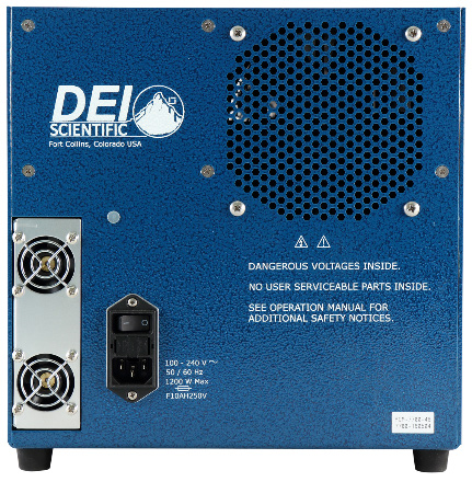
1. Description
The PCM-7700 is an air-cooled, high-power current source designed to drive laser diodes, bars, and arrays. The output current can be set from 5 A to 200 A, with a load voltage of 0 V to 25 V. The pulse width is from 500 µs to 50 ms with a pulse repetition rate of single-shot to 1 kHz.
A front-panel DB-15 connector provides the trigger, current monitor, voltage monitor, current setpoint, and enable connections. An included evaluation board makes all of these signals accessible via BNC cables so the user can begin testing immediately. Output current can be set with a potentiometer on the evaluation board, an analog voltage via a BNC on the board, or directly through DB-15 pin 6. The instrument may be operated in digital control mode (a DC voltage with the pulse width defined by the trigger) or analog control mode (a varying analog voltage sets the output current); either mode requires the user to stay within the SOA curves. The load connects through two twisted-pair cables that preserve the fidelity of high-speed current pulses, and colored front-panel LEDs confirm the system status. The PCM-7700-EX variant requires an external power supply of 0 V to 50 V (there is a 25 V overhead, so it is always the load voltage + 25 V), supplied via a 1-meter cable.
2. Safety & Safe Operating Area
Always refer to the safe operating section for your model. Do not open the cover — there are no user-serviceable parts inside and opening it exposes you to shock and voids the warranty. Do not install, handle, or remove the output cables or laser diode while the unit is operating, and allow at least 10 minutes after power-down before handling them. Allow space for air circulation (cooling air enters the rear and exits the front), and do not use where liquids are present or in corrosive environments.
3. Front Panel Features
| Power LED | Lit when the PCM-7700 power is on (power switch is on the rear). |
|---|---|
| Enable LED | Lit when the output current is enabled; the unit enables only when both Enable 1 and Enable 2 are satisfied. |
| Enable 1 / Enable 2 LEDs | Lit when the first / second enable parameter is met. |
| Over Temperature LED | Lit in an over-temperature condition (disables the output); indicates operation outside the SOA and possible damage. |
| J1 control (DB-15) | Pin 1 Voltage Monitor (1 MΩ, 60 mV/V); Pin 2 Current Monitor (50 Ω, 5 mV/A); Pins 3 & 4 External Enable 2 / Enable 1 (ground to enable); Pin 6 Current Setpoint (10 kΩ, 0–10 V = 0–200 A); Pin 8 Trigger (50 Ω, single-shot to 1 kHz, 0 V off / 5 V on); Pin 14 +12 V output (25 mA, for the evaluation board); remaining pins ground. |
4. Rear Panel Features
The rear panel has an IEC 320 C-14 grounding power connector and the on/off power switch. Accessories included: an IEC 320 C-13 AC power cord; two twisted-pair output cables (Amp 770583-1 connectors on the user end) that transfer output pulses; an evaluation board providing convenient BNC connections to all signals; and an output interface board for mounting the load.
5. Interfacing the Load
The output uses two Amp 1-770974-0 connectors joined to two twisted-pair cables (each output cable is 1 meter, with male Amp 770583-1 connectors — pins 1–8 negative, pins 9–16 positive). The recommended way to interface a load is a simple two-layer PCB with very low resistance and, more importantly, very low inductance to meet the droop and overshoot specifications: use wide copper planes on top and bottom (no inner planes), boards thinner than 0.070″, and 2 oz copper or more. Solder the laser directly to the interface PCB where possible; if wires are necessary, keep them short and twist them if longer than 3 cm. Reducing inductance limits voltage overshoot (V = L · di/dt) — with high currents and fast rise times, even small inductance produces large overshoot. The PCM-7700 also requires DB-15 pins 3 and 4 to be grounded (0 V) to satisfy the enable function.
6. Operation
Setup. With the unit off for at least ten minutes, connect the laser diode with the correct polarity. Make the external trigger connection (DB-15 pin 8 or the evaluation-board BNC; 50 Ω; single-shot to 1 kHz; 0 V off / 5 V on), the control-voltage connection (DB-15 pin 6 or BNC; 10 kΩ; 0–10 V = 0–200 A), and, if desired, the current monitor (pin 2; 50 Ω; 5 mV/A) and voltage monitor (pin 1; 1 MΩ; 60 mV/V). Connect the AC power cord to the rear.
Power up and enable. Verify the external trigger and control voltage are disabled, turn on the rear AC switch (the unit powers up in about 3 seconds and the power LED lights). Set the output current (5–200 A) by applying 0–10 V to the control input, enable the control-voltage source, set the external trigger for the desired frequency (single-shot to 1 kHz) and pulse width (500 µs to 50 ms), and enable the trigger. Set External Enable 1 and Enable 2 to ground (or place switches S1 and S2 on the evaluation board in the Enable position), then view the current and voltage monitors for correct output. Five front-panel LEDs indicate status. Power down: place 5 V on the external enable inputs (or set the board switches to disable), disable the external trigger and control voltage, and turn off the rear AC switch.
7. Warranty & Service
Warranty is 1 Year standard, unless otherwise specified. Materials and workmanship, return to manufacturer included. The warranty does not apply to any product repaired or altered by unauthorized persons, subjected to misuse, neglect, or accident, or used other than in accordance with furnished instructions. Returns must be preauthorized and accompanied by a return-authorization number.
Factory service and support. Berkeley Nucleonics Corporation, 2955 Kerner Blvd., San Rafael, CA 94901. Phone: (415) 453-9955. Email: operations@berkeleynucleonics.com. Web: www.berkeleynucleonics.com.
Cited in peer-reviewed research
Independent publications citing this instrument, indexed by Bioz. Citation counts and Bioz Stars ratings are shown live and update as new papers are indexed.