1The Problem
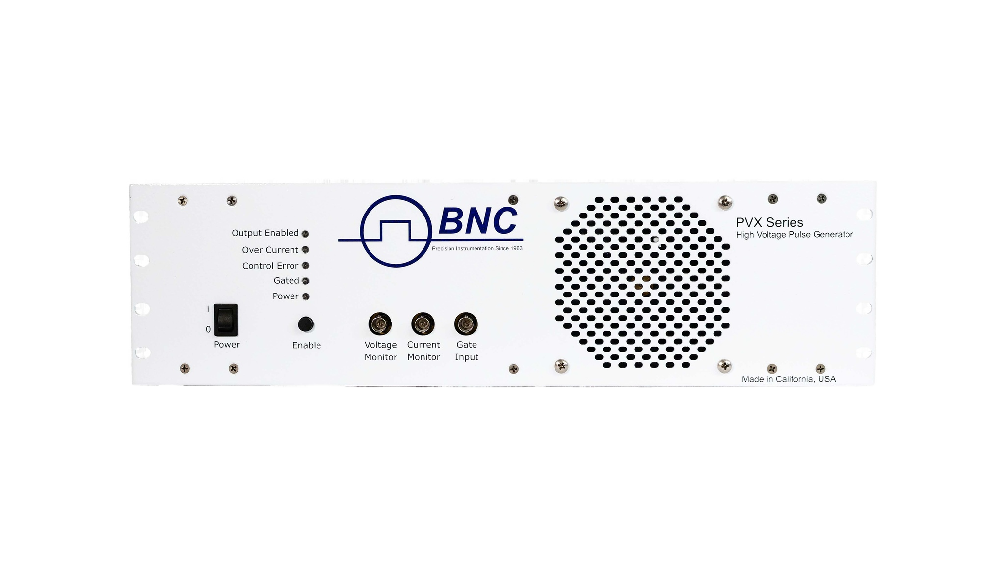
DEI's high-voltage pulse generators for high-impedance and capacitive loads, the PVX-41XX series and the PVM-4210, take two separate DC inputs: a Pulse supply (+HV In, which sets VHIGH) and a Bias supply (-HV In, which sets VLOW). These two supplies may be operated at a common polarity, both positive or both negative, as long as VHIGH stays above VLOW. For example, -HV In at +500 V and +HV In at +1500 V, or -HV In at -1000 V and +HV In at -500 V.
Most high-voltage DC supplies, though, cannot regulate a voltage of the same polarity from a separate source once another supply is already holding the rail near that potential. If the bias (lower-voltage) supply has no additional current path to ground, its output can drift away from its set point when the pulse generator is not gated, charging up toward the potential of the VHIGH supply through leakage current inside the pulse generator. This shows up most often when the load draws little current, or as the pulse repetition frequency increases.
The fix is a current path to ground on the bias input: a shunt resistor for low-power applications, or an active shunt regulator for high-power ones. The rest of this note works through sizing that resistor.
2Why Most DC Supplies Can't Share a Polarity
A positive supply sinks (draws) electrons from ground. A negative supply sources (pushes) electrons to ground. When the Pulse and Bias supplies are of the same polarity, both are trying to move current in the same direction relative to ground, and neither one has the other's cooperation to hold its own rail in place. The lower-voltage bias supply is the one left without a defined return path, because the pulse generator's own internal leakage is the only thing connecting the two rails.
Adding a resistor from the bias input (-HV In) to ground gives that supply somewhere to push or pull current regardless of what the pulse generator is doing, which is what keeps the bias rail at its set point instead of drifting toward VHIGH.
3Sizing the Shunt Resistor
Three things must be known to size the resistor: the maximum pulse repetition frequency, the maximum differential voltage (VHIGH − VLOW), and the total load capacitance, including the load itself, the interconnect cable, and strays.
As the load is capacitive, what charge goes in must also come out. The formula P = C V^2 F, where C is the total load capacitance, V is the differential voltage between VHIGH and VLOW, and F is the pulse repetition frequency, gives the minimum power that must be dissipated in the resistor or shunt regulator from switching the capacitive load.
From that power, the discharge current is I = P / V, where V is the bias (-V) voltage. The shunt resistor value follows as R_SHUNT = V_BIAS / I_HVPS.
Because this bias is not actively regulated by the shunt resistor alone, and can vary with operating parameters, a regulated power supply has to maintain the constant voltage. But if the power supply's own current draw increases beyond the assumed maximum, the bias voltage is no longer controlled by the power supply. Reducing the calculated resistor value by a factor of 2 guarantees that current is always drawn from the bias supply, which keeps regulation intact. The worked example in the next section shows this step.
4Worked Example
Suppose the CV²F calculation for a given load, voltage, and rep rate gives a dissipated power of 1 W, and the bias (-V) voltage is 100 V.
Discharge current. I = P / V = 1 W / 100 V = 10 mA.
Shunt resistor value. R_SHUNT = V_BIAS / I_HVPS = 100 V / 10 mA ≈ 10,000 Ω. Halved for the regulation margin described above, a 5 kΩ resistor would be chosen.
Resistor power dissipation. DC current from the VLOW supply also flows in the shunt resistor. That power is P = V^2 / R, where V is the VLOW voltage and R is the shunt resistor's resistance: P = 100^2 / 5,000 = 2 W.
For reliability, the resistor's power-dissipation capability should be doubled from the calculated value. In this example, that makes the final choice a 5 kΩ, 5 W resistor.
5Resistor Power and Supply Requirements
In determining DC power supply requirements, the VLOW (-HV In) supply must be able to provide the power dissipated in the shunt resistor (2 W, in the example above), and the VHIGH (+HV In) supply must be able to provide the CV^2F power from Section 3.
| Quantity | Relation | Example result |
|---|---|---|
| Discharge current | I = P / V | 10 mA |
| Shunt resistor value | R_SHUNT = V_BIAS / I_HVPS, halved for margin | 5 kΩ |
| Resistor dissipation | P = V_LOW^2 / R, doubled for reliability | 5 W rating |
6When This Doesn't Apply
This potential problem does not occur if the input DC supplies are of different polarities, for example -HV In at -1000 V and +HV In at +500 V, or if one of the DC supply inputs is grounded, for example -HV In connected to ground and +HV In at +1500 V.
Depending on the DC power supply used, at low pulse repetition rates with small capacitive loads, this problem may not be observed at all, because of the small internal paths to ground already found within the DC power supply.
The PVX-41XX series (PVX-4110, PVX-4130, PVX-4141, and PVX-4151) and the PVM-4210 dual-output pulsed voltage module, which shares the same externally-supplied Pulse/Bias architecture and capacitive-load power formula. For the physics behind that formula, see Capacitive-Load Pulsing, and for model selection, Choosing a Pulse Generator.
7Talk to an Engineer
Sizing a shunt resistor or shunt regulator against your own maximum rep rate, differential voltage, and load capacitance is the kind of worked budget that's easiest to get right before the supplies are ordered. For help with the arithmetic for your application, contact a BNC applications engineer.
Contact Berkeley Nucleonics at info@berkeleynucleonics.com or 800-234-7858.