 Powered by Bioz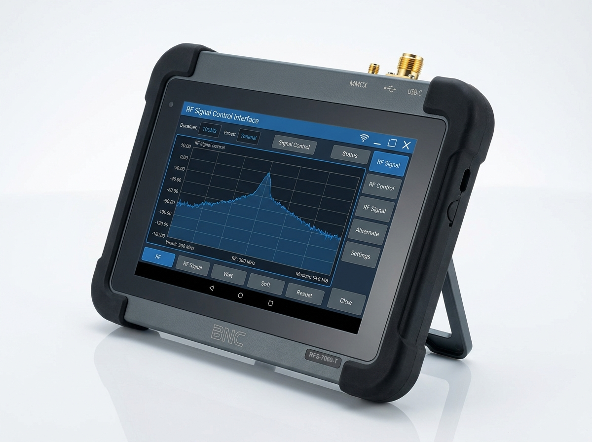
1Version Management
This is the first published edition of the RFS-7060-T User Manual.
| Version | Description | Date | |
|---|---|---|---|
| V1.0 | Initial version. | 10/02/2026 | |
2Safety Instructions
Read these guidelines before using the instrument.
- Appearance inspection: confirm the enclosure is intact and free of damage before use.
- Accessory inspection: check that the power cable and adapter are undamaged.
- Ventilation: keep the fan outlet unobstructed during operation.
- Environment: keep the instrument dry and free of condensation, within the ambient temperature range on the datasheet.
- Connections: connect every external interface correctly, and keep all external input/output signals within the published specifications.
- Battery management: connect the power adapter promptly when the battery runs low.
- Storage: power the instrument off fully before storing it, within the temperature and humidity range on the datasheet.
Power adapter. Use the adapter supplied with the instrument. If a replacement is required, match the voltage, current, and polarity specifications on the datasheet.
3Initial Setup
After long-distance shipping the battery charge may be below 5%. Connect the supplied power adapter before powering on the instrument for the first time.
3.1 Powering On and Off
Press the power button on the top panel to turn the instrument on or off. The power indicator lights when the instrument is on and turns off at shutdown.
3.2 Charging Indicator
The charging indicator flashes green while the battery charges and turns solid green once charging completes.
3.3 Starting VectorCore Studio
Press the power button. Once the instrument finishes booting it loads its desktop environment and launches VectorCore Studio automatically — no separate host PC is required for local operation.
4Interface & Connector Description
Every interface is on the top edge of the instrument for one-handed field use.
| Interface | Description | ||
|---|---|---|---|
| Power button | Turns the instrument on/off. | ||
| Charging port | USB PD 3.0 (65 W). Connect power per the instrument's rated voltage. | ||
| Micro HDMI | External display expansion. | ||
| USB ports (×3) | One USB 3.0, two USB 2.0. Connect external storage, keyboard/mouse, or a driver-free Ethernet hub for remote control. | ||
| Audio output | 3.5 mm headphone jack. Volume is adjustable under System → Parameter Settings → Volume. | ||
| Ethernet port | Gigabit Ethernet. | ||
| Charging indicator | Flashing green: charging. Solid green: charge complete. | ||
| Trigger output | AUXIO connector, 3.3 V CMOS. | ||
| Trigger input | AUXIO connector, 3.3 V CMOS, high impedance, maximum trigger rate 500/s. | ||
| Reference clock input/output | MMCX (F). Input: amplitude ≥ 1.5 Vpp, impedance 200 Ω, accepts sine, square, or clipped-sine signals. Output: 100 MHz, impedance 50 Ω. | ||
| GNSS antenna input | MMCX (F). | ||
| RF signal output | N (F), output impedance 50 Ω. | ||
5Playback Bandwidth & Memory Depth
The instrument supports Playback mode (preloaded into onboard memory) and Streaming mode (data fed continuously from the host). IQ playback bandwidth and waveform memory depth are fixed for this model.
| IQ Playback Bandwidth | Built-in Memory Depth |
|---|---|
| 100 MHz | 128 MB (32 M samples) |
Configure the software or API parameters for your waveform and load the corresponding baseband IQ data for playback. See the VectorCore Studio User Guide for the Playback and Streaming controls themselves.
6GNSS Usage
The instrument has a built-in GNSS module.
- Connect the GNSS antenna to the GNSS antenna input and give it a clear, unobstructed view of the sky. An active antenna with ≥ 30 dB gain is recommended.
- In VectorCore Studio, select System → GNSS Info. Allow 1 to 3 minutes for satellite lock; the pop-up window then reports position, time, satellite count, and SNR.
7Reference Clock Input & Output
7.1 Reference Clock Input
Connect an external reference to the reference clock input/output connector (MMCX, F). In VectorCore Studio, open General Settings → RefCLKSource, select External, and set ExtRefCLKFreq to 10 MHz.
7.2 Reference Clock Output
Connect to the same reference clock input/output connector. In VectorCore Studio, open General Settings and enable RefCLKOut to output a 100 MHz clock.
8Remote Control
The instrument's own VectorCore Studio session and a host PC's copy of the software cannot run at the same time — exit the on-instrument software (File → Exit) before connecting from a PC.
8.1 Direct Ethernet Connection
- Copy the calibration files from the instrument's
/software/VectorCoreStudio/bin/CalFiledirectory into the matching/bin/CalFiledirectory of the PC-side software install. - Connect the instrument's Ethernet port directly to the PC's Ethernet port.
- On the PC, set a manual IPv4 address and subnet mask on the same segment as the instrument (the instrument default is
192.168.1.100). - Verify the link with
ping 192.168.1.100from a command prompt. - Launch VectorCore Studio on the PC, then select Device → ETH Connect, confirm the IP address, and click Connect.
8.2 Local Area Network (LAN) Connection
- Connect the instrument's Ethernet port to a router.
- Exit the on-instrument software, copy its
/software/VectorCoreStudio/bin/CalFilecontents to the PC-side install as above, then check the instrument's assigned IP address from its own terminal (ifconfig). - Join the PC to the same network, launch VectorCore Studio, select Device → ETH Connect, enter the instrument's IP address, and click Connect.
9Software Operation
Every control, waveform type, and modulation setting in VectorCore Studio — CW, Playback, and Streaming modes; AM/FM/pulse/digital-ramp/AWGN generation; digital modulation, DSSS, and OFDM; configuration files; firmware update — is documented once, shared with the RFS-7060-U, in the VectorCore Studio User Guide.
Cited in peer-reviewed research
Independent publications citing this instrument, indexed by Bioz. Citation counts and Bioz Stars ratings are shown live and update as new papers are indexed.