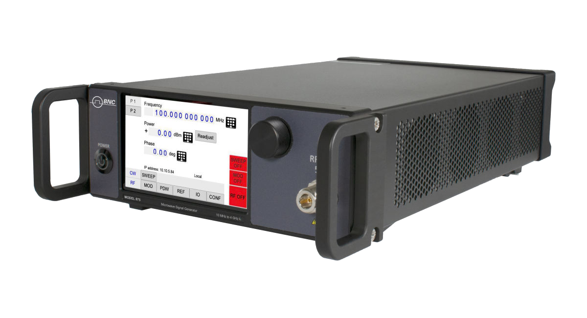
SAN RAFAEL, Calif., August 31, 2026. Berkeley Nucleonics Corporation (BNC) is highlighting the Model 875 Vector Signal Generator as a purpose-built source for electronic warfare and radar test, where the signal environment refuses to sit still. The Model 875 covers 10 MHz to 40 GHz continuously, plays back a live sequence of radar and threat pulses through its Pulse Descriptor Word engine, and holds phase across up to four channels while it does it.
Modern EW and radar test rarely asks for one clean tone. It asks for a scene: several emitters, each hopping frequency, changing power, and switching phase on a schedule measured in nanoseconds, sometimes on top of each other. A generator built for one carrier at a time cannot produce that scene. It can approximate a single threat. It cannot recreate the crowded, agile spectrum a receiver, a jammer, or an operator actually has to sort through.
The Model 875 was built around that gap. Its Pulse Descriptor Word (PDW) engine takes direct control of the RF output, pulse by pulse, and plays a programmed list or a live stream of frequency, power, phase, timing, and waveform changes with the timing accuracy a threat library demands.
Real-time pulse control, not simulated after the fact
Every pulse in a PDW simulation carries its own start time, width, frequency, power, phase, and waveform segment ID. The Model 875 accepts these as a list, uploaded in advance as a CSV file or built and stored on the instrument, or as a live stream through the Fast Control Port (option FCP), which lets a test computer inject or change PDWs while the simulation is already running. A list can hold up to 65 million PDWs and buffer up to 1,024 of them ahead of playback, so a long, varied threat sequence runs without a gap.
Timing resolution is 8 nanoseconds. Pulse width can run as short as 8 nanoseconds with the ultra-fast switching option (UFS), and RF frequency and phase are settable on every pulse across the instrument’s full range, at a resolution of roughly two-thousandths of a hertz and 0.0055 degrees respectively. Pulse edges rise and fall in 5 nanoseconds. None of it is simulated after the fact. Every parameter changes on the RF output itself, in real time, on the schedule the list or the stream sets.
Four channels, one phase reference
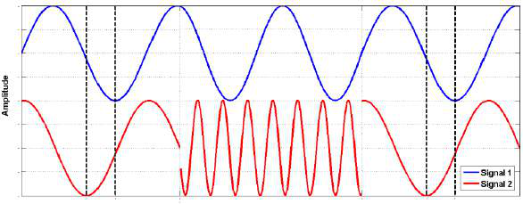
A realistic EW scene rarely comes from a single emitter. The Model 875 is built as a multi-channel product, up to four channels in one chassis, and each channel can run its own independent PDW simulation while staying phase-referenced to the others.
With phase-coherent switching (option PHS), the relative phase between channels is deterministic and reproducible: for any given combination of frequency and power settings, two channels return to the same relative phase every time, even across a power cycle. Phase memory goes further. A channel that switches away and back behaves as if it never left, as if it were a continuously running source the whole time. Channel-to-channel isolation runs above 90 dB, and channel-to-channel jitter is typically within ±10 picoseconds. Option SYNC extends that same coherence across multiple Model 875 chassis, so a scene that needs more than four coordinated emitters scales by adding units, not by giving up the phase relationship that makes the simulation credible.
Clean enough to trust
None of the timing precision would matter if the signal itself were noisy. SSB phase noise at 1 GHz runs to -145 dBc/Hz at a 20 kHz offset, tightening to -150 dBc/Hz at 100 kHz, figures that keep a receiver’s own noise floor as the limiting factor rather than the source driving it.
Underneath the PDW engine sits a full vector signal generator. The internal I/Q modulator plays arbitrary waveforms from up to 512 megasamples of onboard memory, streams live I/Q data through the Fast Control Port, and supports internal avionics modulation formats directly (option AVIO), extending PDW-style simulation into avionics EW test. An onboard additive white Gaussian noise generator (option AWGN) layers a realistic noise floor under any simulation, and external analog I and Q inputs (option AIQ) accept outside baseband sources when the test calls for them.
Key specifications
- Continuous coverage from 10 MHz (100 kHz with option 100K) to 4, 6, 12, 20, or 40 GHz depending on model, with 0.001 Hz frequency resolution
- Real-time Pulse Descriptor Word engine: List mode (up to 65 million PDWs, 1,024-PDW buffer) or live Stream mode over the Fast Control Port; 8 ns timing resolution, pulse width to 8 ns with option UFS
- Up to 4 phase-coherent channels per chassis; phase-coherent switching and phase memory (option PHS); multi-device synchronization to scale beyond 4 channels (option SYNC)
- SSB phase noise to -145 dBc/Hz at 1 GHz, 20 kHz offset; better than -150 dBc/Hz at 100 kHz offset
- 400 MHz RF modulation bandwidth; internal I/Q modulator with up to 512 MS of waveform memory, 10 Hz to 500 MHz sample rate at 16-bit resolution
- Avionics modulation (option AVIO), AWGN noise generation (option AWGN), and external analog I/Q inputs (option AIQ) for extended simulation scenarios
- Ethernet, USB 2.0, and optional GPIB remote control; internal OCXO reference with external reference input
“A modern EW receiver has to make sense of a dozen things happening at once, on a schedule measured in nanoseconds,” said John Lauder, Chief Technical Officer at Berkeley Nucleonics. “The Model 875 was built to recreate that, pulse by pulse, phase-coherent across every channel, so a test lab can trust that what the receiver sees on the bench is what it will see in the field.”
Berkeley Nucleonics has supplied signal generation to defense, research, and industrial customers for more than sixty years, and the Model 875 sees regular use in:
- Radar and EW threat simulation, driving frequency-agile, phase-coherent pulse trains that stand in for real emitters
- EW receiver testing, including dense, multi-emitter scenes built from concurrent PDW channels
- Avionic modulation emulation, using the AVIO option
- High-speed antenna testing, where fast, phase-coherent switching across channels matters as much as raw frequency coverage
- General radar signal simulation and receiver testing outside the EW mission, from chirped pulses to standard modulation and sweep work
Availability
The Model 875 is available now in 4, 6, 12, 20, and 40 GHz variants, configured to order from the option set above. Full specifications, the complete option list, and a quote request are on the Model 875 datasheet page.
About Berkeley Nucleonics
Berkeley Nucleonics Corporation (BNC) has been a trusted name in precision electronic instrumentation since 1963, serving defense, research, academic, and industrial customers with digital delay generators, arbitrary waveform generators, RF/microwave signal generators, pulsed power systems, and nuclear radiation detection equipment. With 60+ years of reliability and responsive technical support, BNC is flexible and listens to your application.
Media contact
Ian Parnes
Berkeley Nucleonics Corporation
ian.parnes@berkeleynucleonics.com
800-234-7858
Technical contact: Amira Sekkouty, amira.sekkouty@berkeleynucleonics.com