 Powered by Bioz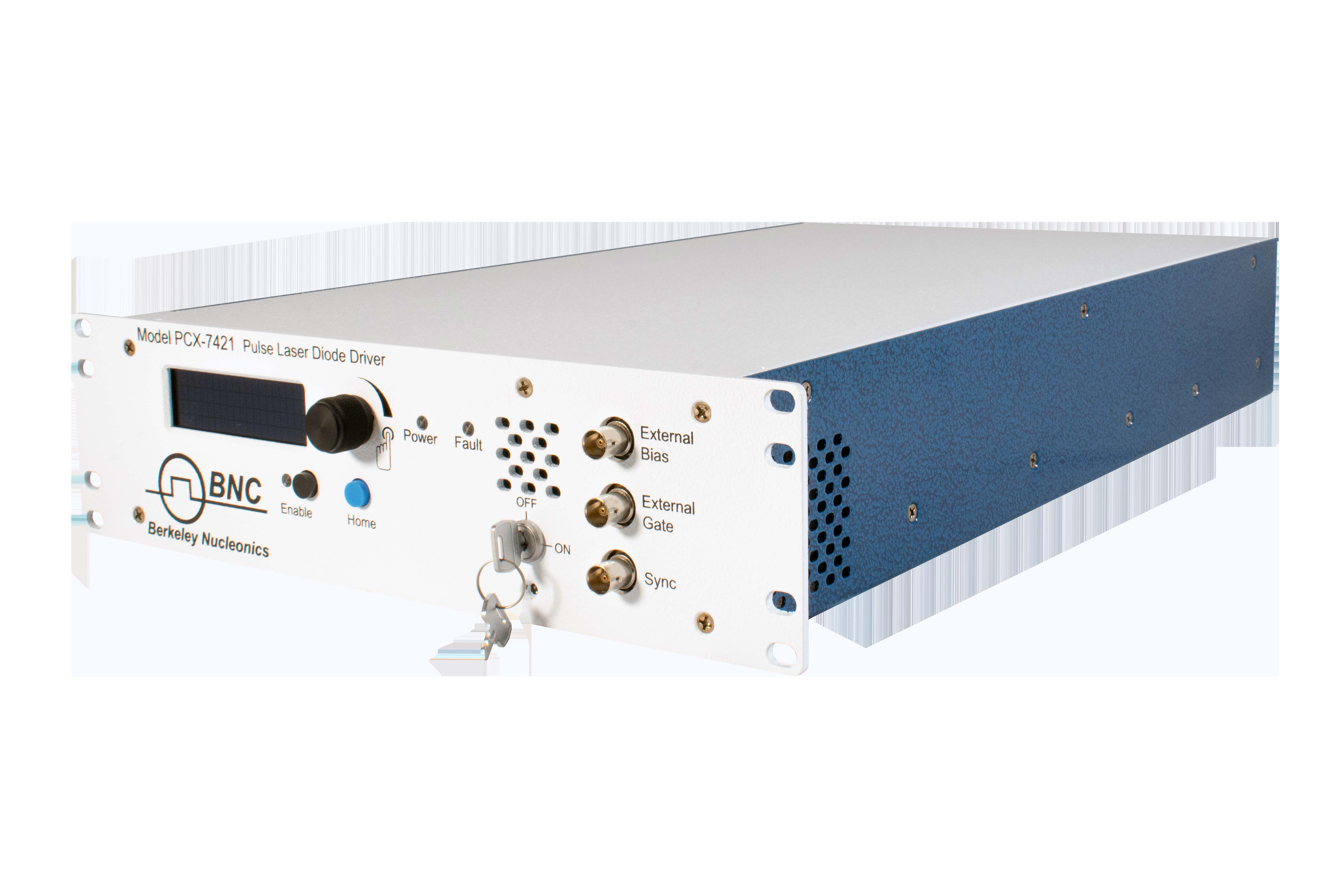
1. Description
The PCX-7421 is a pulsed current source designed to drive laser diodes, bars, and arrays. It delivers current pulses from 3 A to 21.5 A with up to 250 W of total output power. An internal trigger source provides pulse repetition frequencies from 40 Hz to 100 kHz, and the external trigger function allows operation from single-shot to 1 MHz. The bias current, main output current, bias pulse width, main pulse width, trigger source, and trigger frequency are adjustable from the front-panel OLED screen or by computer via the RS-232 or USB interface.
The bias feature delivers the current pulse in two steps. The bias pulse starts before the intended trigger time with current set just below the lasing point, minimizing the diode’s response time to the main pulse; it is adjustable from 0 A to 5.8 A with a pulse width from 0 ms to 25 ms. The main pulse current adds to the bias current and energizes the diode at the intended time; it is adjustable from 3 A to 15.7 A with a pulse width from 50 ns to 5 ms. The total output pulse is always the sum of the bias and main pulse currents, even if the bias width is set to zero.
The PCX-7421 can be triggered internally or externally; the input termination for both the external gate and external bias gate is selectable for 50 Ω or 10000 Ω. The front-panel Sync output (logic levels 0 V and +5 V) has a rising edge coincident with the main output current pulse, with a delay of 5 ns to 15 ns.
2. Safety
Do not open the cover of the PCX-7421; there are no user-serviceable parts inside and opening it exposes you to lethal shock and voids the warranty. Do not install, handle, or remove the output cable or laser diode while the unit is operating. The PCX-7421 can be triggered randomly by spurious transients — always assume an unexpected pulse can appear at the output. Allow at least 10 minutes after power-down before handling the output cable or laser diode. Allow sufficient space for air circulation (cooling air enters the front and exits the back), protect the device against liquid entry and corrosive environments, and clean it by wiping with a dry or damp cloth.
3. Front Panel Features
| HOME button | Returns the display to the Home screen (Main Current, Bias Current, Rear Enable status, Key Switch status). |
|---|---|
| ENABLE button | Toggles between enabled and disabled; illuminates green when enabled, red when disabled. |
| OLED screen | Provides the user interface. |
| Encoder knob | Rotate to change a value; push to cycle through resolutions. Press HOME to exit a parameter screen. |
| Keyswitch | ON allows the unit to be enabled; OFF disables it and prevents enabling. |
| External Bias / External Gate inputs | BNC connectors accepting bias and trigger pulses from an external source. Their impedance is selectable together to 50 Ω or 10 kΩ. |
| Sync output | BNC connector providing synchronizing pulses coincident with the leading edge of the output current pulse. |
4. Rear Panel Features
| Output | Accepts the factory-supplied output cable and provides the generated current pulses. Do not touch this cable while powered up. |
|---|---|
| Rear Enable | Accepts an external dry-contact closure or the factory-supplied shorting BNC plug. Closing the contacts or installing the plug enables the output; opening or removing it disables the output and creates a rear-enable fault. |
| IMON output | BNC connector providing a voltage proportional to the output current. Never connect an oscilloscope directly to the output of the system. |
| USB / RS-232 | Communication with an external computer via USB or an RS-232 null cable. |
| Power connector, fuse holder & switch | Standard grounding power cable; the fuse holder houses two AC fuses; the on/off switch powers the unit. |
5. Accessories & Output Cable
Included accessories: AC power cable (NEMA C14 to NEMA 5-15R); shorting BNC plug for the Rear Enable connector; keyswitch keys; two factory-supplied output cables that provide high current pulses to the external device; and a laser output PCBA that provides a simple method to interface a laser or other external device.
The two male Amp connectors (770583-1) interface with the instrument. On each connector, pins 1 through 8 are the negative (−) output and pins 9 through 16 are the positive (+) output.
6. Operation
Setup. Make sure the unit has been off for at least ten minutes and the diode connection polarity is correct. Connect the output cable from the PCX-7421 to the output device, make any other connections (External Trigger, External Bias, Sync, IMON, computer), and connect the Rear Enable BNC and power cable.
Power up. Turn the power switch ON; the unit displays system information, serial number, and firmware revisions, then shows the Home screen (Main Current, Bias Current, Rear Enable, Key Switch). Turn the keyswitch ON when ready to turn on the output pulse.
Set main and bias current. Rotate the encoder to the Main Current or Bias Current screen, press the knob to update, rotate to change the value (main 3 A to 15.7 A; bias 0 A to 5.8 A), and press the knob to change the multiplier (×0.001 to ×10.000). Press HOME when done. Commands: MAIN:CURRENT:SETPOINT and BIAS:CURRENT:SETPOINT.
Set pulse widths. Rotate to the Main Pulsewidth or Bias Pulsewidth screen and set the value (main 0.100 µs to 5000 µs; bias 0 µs to 25000 µs); the resolution depends on frequency (6400 ns from 40–300 Hz, 1600 ns from 300–5000 Hz, 100 ns from 5–100 kHz). Commands: TRIG:INT:MAIN:PULSEWIDTH and TRIG:INT:BIAS:PULSEWIDTH. For external operation, set the pulse width on the external signal generator.
Trigger, termination, and frequency. Set the trigger source to Internal or External Gate on the Trigger Type screen (TRIG:INTERNAL / TRIG:EXTERNAL); disable the system before switching. For external triggering, set the termination to 50 Ω or 10 kΩ (TRIG:EXT:TERM). Set the internal frequency from 40 Hz to 100000 Hz (TRIG:INT:FREQ); when the frequency changes, the duty cycle is maintained, so change the frequency first and then the pulse width.
Save, recall, and power down. Use the Save Settings and Recall Settings screens to store or restore memory locations 1–5 (*SAVE n, *RECALL n); at power-up the system defaults to location 1. To power down, disable the unit (ENABLE button or OUTPUT:DISABLE), turn the keyswitch OFF, and switch the unit off at the rear.
7. Warnings & Faults
All faults disable the PCX-7421. To continue after clearing a fault, send OUTPUT:ENABLE from the computer or press the ENABLE button.
| Keyswitch fault | The keyswitch was OFF at power-up or turned OFF during operation. Turn the keyswitch ON to continue. Query STATUS:KEYSWITCH?. |
|---|---|
| Rear enable fault | Caused by open dry contacts in the rear-enable circuit or removal of the shorting BNC plug. Connect the dry contacts or install the shorting plug. Query STATUS:REAR:ENABLE?. |
| Over-temperature fault | The ambient (intake) or exhaust air temperature exceeded the safe range. Allow cool, free air to flow front-to-rear. View temperatures with TEMP:IN? and TEMP:EXHAUST?. |
Communication. RS-232 and USB share the same settings: 115200 baud, 8 data bits, no parity, 1 stop bit, no flow control; the end-of-data character is the ASCII newline. RS-232 is selected by default; connecting the USB port to a computer disables RS-232 automatically.
8. Command Set
A host PC controls the PCX-7421 through its RS-232 or USB interface. The command set is based on SCPI. Commands and queries must be in all capital letters; those requiring data (n) need a space before the data. The unit returns a response for every command — wait for it before sending the next. Any change typically requires less than 200 ms.
| Command / Query | Function |
|---|---|
*IDN? | Returns manufacturer, model, serial number, firmware revisions, and manufacture date. |
*LIST? | Lists all supported commands and queries. |
*SAVE n / *RECALL n | Saves or recalls a configuration; n = 1 to 5. |
OUTPUT? / OUTPUT:ENABLE / OUTPUT:DISABLE | Returns, enables, or disables the output. |
TRIG? / TRIG:INTERNAL / TRIG:EXTERNAL | Returns or sets the trigger source (internal or external). |
TRIG:EXT:TERM? / TRIG:EXT:TERM n | Returns or sets external-trigger termination (n = 50 or 10k). |
TRIG:INT:FREQ? / TRIG:INT:FREQ n | Returns or sets internal trigger frequency in Hz (n = 40 to 100000). |
TRIG:INT:MAIN:PULSEWIDTH? / … n | Returns or sets main pulse width in ns (n = 50 to 5,000,000). |
TRIG:INT:BIAS:PULSEWIDTH? / … n | Returns or sets bias pulse width in ns (n = 0 to 25,000,000). |
MAIN:CURRENT:SETPOINT? / … n | Returns or sets main current in mA (n = 3000 to 15700). |
BIAS:CURRENT:SETPOINT? / … n | Returns or sets bias current in mA (n = 0 to 5800). |
STATUS:KEYSWITCH? / STATUS:REAR:ENABLE? | Returns the state of the keyswitch and rear enable. |
TEMP:IN? / TEMP:EXHAUST? | Returns the intake and exhaust air temperatures in °C. |
9. Warranty & Service
Warranty is 1 Year standard, unless otherwise specified. Materials and workmanship, return to manufacturer included. The warranty does not apply to any product repaired or altered by unauthorized persons, subjected to misuse, neglect, or accident, or used other than in accordance with BNC instructions. Returns must be preauthorized and accompanied by a BNC return-authorization number.
Factory service and support. Berkeley Nucleonics Corporation, 2955 Kerner Blvd. #D, San Rafael, CA 94901. Phone: (415) 453-9955. Email: operations@berkeleynucleonics.com. Web: www.berkeleynucleonics.com. Document version 7650-0037 Rev A2.
Cited in peer-reviewed research
Independent publications citing this instrument, indexed by Bioz. Citation counts and Bioz Stars ratings are shown live and update as new papers are indexed.