 Powered by Bioz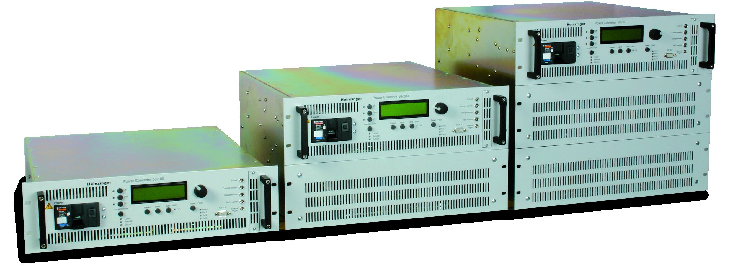
1Overview
The PCU series is a family of high-precision magnet power supplies offered through Berkeley Nucleonics. The switch-mode units provide high-precision DC voltage with current stability and extremely low ripple, optimized for use as power supplies for magnets. They are available in typical voltage categories with a modular design, with various currents between 100 A and 340 A for each supply.
The supplies achieve maximum accuracy and stability of 5 ppm, with a temperature coefficient of 5 ppm or better, DCCT current measurement, and a programmable current ramp function. Performance classes extend as high as 15 kW, with higher power available on request. In applications requiring more power, the supplies can be used in master/slave mode in parallel for multiplication of power.
PCU supplies are used at well-known research institutes as reliable magnet power supplies in 24/7 operation. The ratio between power density and maximum precision keeps the unit within its specified technical limits in demanding, long-term applications. Many manual operating and programming features make it straightforward to customize a unit across a wide range of load conditions. The analog and digital interfaces, both available as standard, let you read and write values to the supply in a variety of remote control applications.
2Specifications
Model Matrix
Each PCU model is identified by its nominal voltage and current class. Four standard members span the family, from 5 kW through 15 kW at 50 V, plus a 30 V, 340 A class.
| Model (PCU) | 50-100 | 50-200 | 50-300 | 30-340 |
|---|---|---|---|---|
| Nominal output current (A) | 100 | 200 | 300 | 340 |
| Nominal output voltage (V) | 50 | 50 | 50 | 30 |
| Nominal output power (W) | 5000 | 10,000 | 15,000 | 10,000 |
| Absolute current accuracy deviation | 2 mA | 4 mA | 6 mA | 7 mA |
| Current reproducibility deviation | 5 mA | 10 mA | 15 mA | 7 mA |
Common Specifications
The following parameters apply across the PCU family.
| Parameter | Specification |
|---|---|
| Line input voltage (V) ±10 % | 400 / 3-phase; 47 to 63 Hz (other on request) |
| Ambient temperature | 0 to 40 °C |
| Minimum efficiency | ≥90 % |
| Power factor | ≥90 % |
| Setting range | 1 to 100 % |
| Regulation mode | CC or CV mode, selectable |
| Ramp function | Programmable di/dt ramp function |
| Current loop adjustment | Via plug-on components |
| DAC resolution | 16 bit |
| ADC resolution | 16 bit |
| Rise time (10 to 90 %), full load | Depending on load (R, L), typically 30 ms |
| Residual voltage ripple p/p up to 10 kHz | 200 to 300 mV |
| Current deviation for ±10 % of mains variation | ≤5 ppm |
| Current deviation for ±10 % of load variation | ≤5 ppm |
| Current stability over 8 hours | ≤6 ppm |
| Current deviation in temperature | ≤5 ppm/°C |
| MTBF | ≥100,000 hrs |
| Input/output insulation (kV r.m.s., 1 min) | 2.3 |
| Cooling | Air cooling (water cooled optionally) |
3Control & Interfaces
The PCU offers analog and digital control paths, both available as standard. The 0 to 10 V analog interface handles current and voltage measuring and setting. The RS422 digital interface adds the same measuring and setting functions along with output ON/OFF with status, failure and reset alarm indication, and polarity indication. A programmable di/dt ramp function controls how the output current changes over time, and the current loop is adjusted via plug-on components.
| Function | Specification |
|---|---|
| Analog interface | 0 to 10 V analog interface for current and voltage measuring and setting |
| Digital interface | RS422 digital interface for current and voltage measuring and setting; output ON/OFF with status; indication and reset of alarms; polarity indication |
| Displays | 2-line LCD display: 5 digits for current, 4 digits for voltage, CC or CV mode, alarm message; LED indications for failures |
| Ramp function | Programmable di/dt ramp function |
| Current loop adjustment | Via plug-on components |
| DAC resolution | 16 bit |
| ADC resolution | 16 bit |
4Protection & Reliability
The PCU is short circuit proof. Alarm conditions are surfaced on the front panel through LED failure indications and a 2-line LCD alarm message, and the RS422 interface reports failures with status and reset of alarms. The supplies are built for 24/7 operation, with an MTBF of 100,000 hours or better.
| Parameter | Specification |
|---|---|
| Short circuit | Short circuit proof |
| Input/output insulation | 2.3 kV r.m.s., 1 min |
| MTBF | ≥100,000 hrs |
| Cooling | Air cooling (water cooled optionally) |
| Alarms | LED failure indications; LCD alarm message; failure/reset alarm reporting over RS422; polarity indication |
5Applications
The PCU is built for magnet power and other applications demanding the highest quality, precision, and accuracy. Typical uses include:
- Semiconductor tests and manufacturing
- HV tests
- Quality tests
- Mass spectrometer detectors
- Accelerators (kickers, detectors)
For programmable benchtop high-voltage DC, see the HVX-Series.
6Ordering Information
Specify the model by voltage and current class (50-100, 50-200, 50-300, or 30-340). Additional voltage and current combinations and customer-specific variants are available on request.
Accessories & Options
- Water-cooled variant on request
- Master/slave configuration: a PCU master unit and a PCS slave unit for multiplication of power
- Redundant units (n+1 redundancy)
- Pole reversal unit for switching polarity
- Plug-in card for changing controller settings
- Customer-specific variants
- Additional voltage and current combinations
Contact
For a quote, a configuration matched to your load, or application support, reach the Berkeley Nucleonics team.
Email: info@berkeleynucleonics.com
Phone: 800-234-7858
Cited in peer-reviewed research
Independent publications citing this instrument, indexed by Bioz. Citation counts and Bioz Stars ratings are shown live and update as new papers are indexed.