1Purpose
This application note describes the automatic level control (ALC) system of Berkeley Nucleonics (BNC) Signal Generators such as the Model 845, 855B, 865B and 875.
It provides information about different ALC modes and ALC programming commands.
2Introduction
BNC Signal Generators use an automatic level control (ALC) system to hold the output power at its programmed value. The ALC compensates the effect of ambient conditions such as temperature on output power.
The ALC continuously monitors output power, compares it to the programmed setting and corrects output power if needed.

The ALC has an impact on amplitude noise, modulations and on switching speed. Different applications impose different requirements on the ALC. Selectable ALC modes are available to optimize performance.
3ALC modes
Three ALC modes with different limitations and benefits are available:
- ALC on, hold off
- ALC on, hold on
- ALC off
ALC on, hold off is the default mode for CW operation. The ALC continuously monitors and corrects output power.
This mode guarantees output power meets specifications.
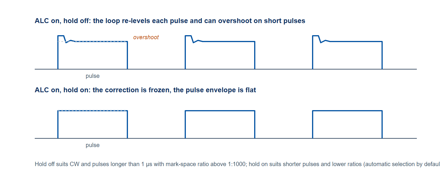
This is the preferred mode for CW operation and for pulsed signals with moderate mark-space ratio (> 1:1000) and with long pulse duration (> 1 µs).
When used with short pulses or extreme mark-space ratios, output power accuracy degrades and overshoot may occur.
ALC on, hold on stops continuous output power correction.
Effects of ambient conditions on output power are no longer corrected.
Output power typically still meets specifications but this is not guaranteed as conditions like internal temperature may vary.
When changing output power or frequency in this mode, the Signal Generator has to return to ALC on, hold off to sample the new power correction control signal. Thus this mode increases CW switching time.
Sweeps in ALC on, hold on mode sample the power correction control signal for each point in advance. Thus setting up a sweep takes more time than in hold off mode (about 2 ms per point).
This is the preferred mode for pulse signals with low mark-space ratio (< 1:1000) or with short pulse duration (< 1 µs).
ALC off disables the complete ALC system.
Output power range and resolution degrade. Specified accuracy is not guaranteed.
This mode may be used in applications where lowest amplitude noise is important and limited power range and accuracy are acceptable.
4ALC bandwidth
The bandwidth of the power correction loop is adjustable.
Low bandwidth provides best amplitude noise performance but also long amplitude settling time.
Low bandwidth is preferred for CW operation.
Typical settling time is between 10 ms and 1 s, depending on the model.
High bandwidth provides low amplitude settling times at the cost of increased amplitude noise.
High bandwidth is preferred for swept operation or for pulse modulation under ALC on, hold off.
Typical settling time is about 10 µs.
5ALC settings for pulse modulation and pulsed sweeps
The ALC configuration has an effect on pulse modulation and pulsed sweeps.
The ALC is designed such that it can level pulsed signals. However, power overshoot may occur when a pulse starts, particularly when playing short pulses or low mark-space ratios.
Power overshoot can be reduced in time using high ALC bandwidth or eliminated completely using ALC on, hold mode.
6Automatic ALC mode and bandwidth selection
A BNC Signal Generator can automatically choose ALC mode and bandwidth for any operation mode. This automatic mode is active by default:
| Operation mode | ALC mode | ALC bandwidth |
|---|---|---|
| CW | on, active | low |
| Sweep | on, active | high |
| Pulse >= 1 µs | on, active | high |
| Pulse < 1 µs | on, hold | (high)* |
Table 1: Automatic ALC mode and bandwidth selection
* ALC bandwidth setting has no effect while in hold mode. However, high bandwidth is used to sample the power correction control signal when changing frequency or power.
Programming user specific settings disables automatic mode and bandwidth selections. However automatic mode and bandwidth can be enabled again any time by sending reset or automatic enable commands.
7ALC mode and bandwidth commands and queries
*RSTResets the device to factory default settings. This enables the ALC system and automatic ALC mode and bandwidth selection.
[:SOUR]:POW:ALC?
[:SOUR]:POW:ALC 0|OFF|1|ON
Enables or disables the ALC system.
*RST value: ON
[:SOUR]:POW:ALC:HOLD?
[:SOUR]:POW:ALC:HOLD 0|OFF|1|ON
Enables or disables ALC hold mode.
This setting has no effect if the ALC system is disabled (see [:SOUR]:POW:ALC).
Programming this setting disables automatic hold mode selection. The device can change this setting automatically. (see [:SOUR]:POW:ALC:HOLD:AUTO)
*RST value: (automatic)
[:SOUR]:POW:ALC:HOLD:AUTO?
[:SOUR]:POW:ALC:HOLD:AUTO 0|OFF|1|ON
Enables or disables automatic ALC hold mode state selection.
Enabling automatic mode also changes the hold mode selection according to table 1.
Programming the ALC hold mode disables automatic mode. (see [:SOUR]:POW:ALC:HOLD)
*RST value: ON
[:SOUR]:POW:ALC:BWID?
[:SOUR]:POW:ALC:BWID LOW|HIGH
Sets the ALC bandwidth.
This setting has no effect if the ALC system is disabled (see [:SOUR]:POW:ALC). In hold mode (see [:SOUR]:POW:ALC:HOLD), this setting only affects the sampling of the power correction control signal upon frequency or power changes.
Programming this setting disables automatic bandwidth selection. The device can change this setting automatically. (see [:SOUR]:POW:ALC:BWID:AUTO)
*RST value: (automatic)
[:SOUR]:POW:ALC:BWID:AUTO?
[:SOUR]:POW:ALC:BWID:AUTO 0|OFF|1|ON
Enables or disables automatic ALC bandwidth selection.
Enabling automatic mode also changes the bandwidth selection according to table 1.
Programming the ALC bandwidth disables automatic mode. (see [:SOUR]:POW:ALC:BWID)
*RST value: ON