1Purpose
This application note reports the measured channel-to-channel and unit-to-unit phase stability of the Model 855B multi-channel Signal Generator.
2Introduction
Early frequency synthesizers were not necessarily controlled by a single crystal standard. Adequate frequency stability was obtained using several internal crystal oscillators that contributed to the overall frequency stability of the output. These devices were considered non-coherent. As applied to frequency synthesizers, phase coherence describes the relation of the frequency standard to the output frequency. If the output frequency accurately reproduces the relative frequency stability of the standard, the device is considered coherent. Despite this definition, the assumption that all contemporary systems that use a single standard (external or internal) are coherent is incorrect. Many systems that utilize fractional-N or binary DDS fine-resolution synthesizers are not truly phase coherent; rather they have specified small but finite reference-to-output errors.
What is of particular interest is the phase stability observed over a long period of time between two independent signal sources that are phase locked to the same external (usually 10 MHz) reference.
This application note shows the phase coherence of the Model 855B multi-output Signal Generator, whose channels share one reference and whose modules can be synchronized to each other and to an external reference.
The Model 855B is available with frequency ranges of 300 kHz to 6, 12, 20, 33 or 40 GHz and up to four channels in a 1U module. Each channel can be programmed independently in frequency, phase (0 to 360 degrees in 0.1 degree steps), amplitude and modulation.
3Test Setups
Figure 1a shows the test setup to determine the level of phase stability (coherence) between two individual outputs of a single instrument. A phase detector and a digital oscilloscope are used to monitor the phase stability between two RF channels over a long time interval, in this case approx. 24 hours. All tests were performed at 20°C ± 1°C.
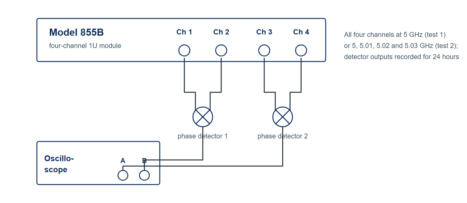
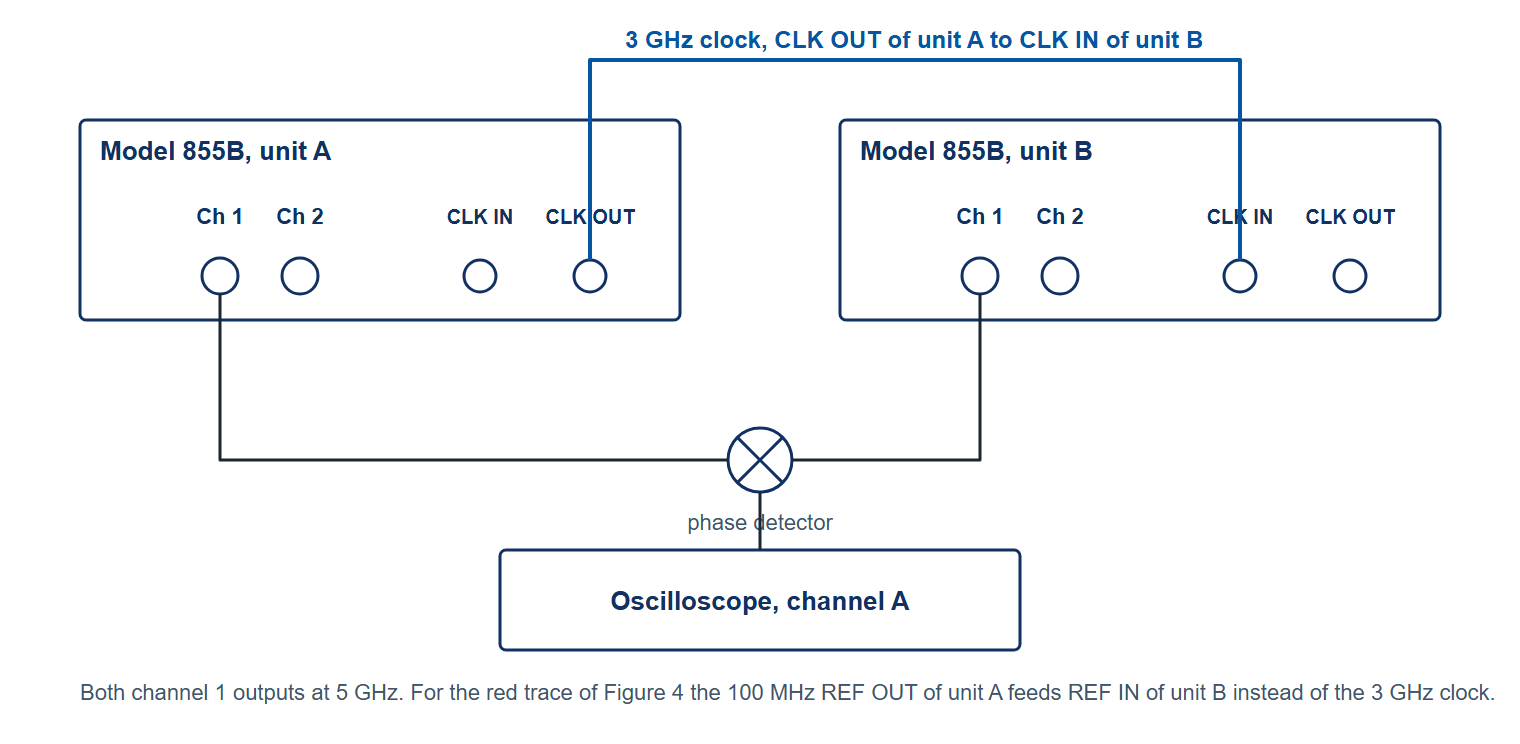
Figure 1b shows the test setup to measure phase stability between two outputs from two separate 855B units.
4Test 1: Phase coherence of one 855B at the same frequency on all channels
Based on the test setup in Figure 1a, all channels are set to 5 GHz. The signals of channels 1 and 2 are fed into a first phase detector while channels 3 and 4 are fed into a second phase detector. Phases of channel 1 and 3 are subsequently adjusted to achieve phase quadrature at the phase detector inputs. The output signals of both detectors are measured simultaneously on the two channels of the oscilloscope. The measurement is made over 24 hours.

As Figure 2 shows, the relative phase between channels stays within a few milliradians over 24 hours; the datasheet specifies 3 mrad at 5 GHz over 5 hours. For comparison, locking a second unit through the standard 100 MHz reference instead of the 3 GHz clock produces a drift of roughly 30 mrad over 10 hours (Figure 4, red trace).
5Test 2: Phase coherence of one 855B at different frequencies
Based on the test setup in Figure 1a, channel 1 is set to 5 GHz, channel 2 to 5.01 GHz, channel 3 to 5.02 GHz and channel 4 to 5.03 GHz. The signals of channels 1 and 2 are fed into a first phase detector while channels 3 and 4 are fed into a second phase detector. The channels are adjusted in phase such that the two 10 MHz output signals of the phase detectors show a 180 degree phase shift.
The output signals of both detectors are then measured simultaneously on 2 channels of the oscilloscope. The oscilloscope is set to persistence mode and the measurement is continuously triggered on the rising slope of the signal on channel A. The measurement is done over a period of 24 hours.
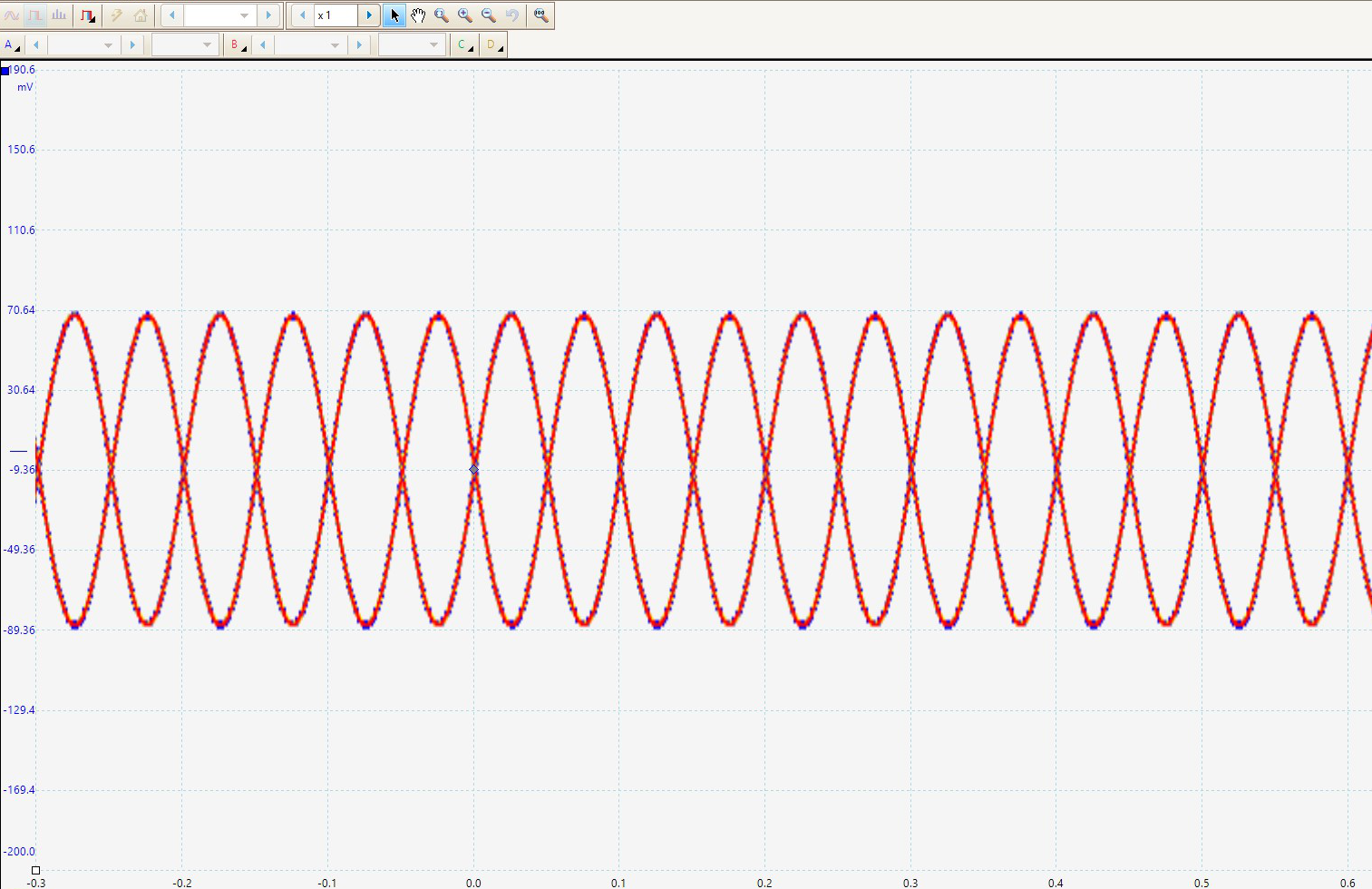
As Figure 3 shows, after 24 hours no phase drift is visible between the two traces, which means the 10 MHz difference frequencies synthesized on the four channels are exact.
6Test 3: Phase coherence between multiple 855B units using the 3 GHz clock synchronization
Some applications require more than four outputs that hold their phase relationship over a long period. The 855B provides dedicated 3 GHz CLK IN and CLK OUT ports so that a cascaded group of 855B units can share one high frequency clock.
Figure 4 shows the channel-to-channel phase stability within one unit (blue trace), the unit-to-unit stability when two 855B units are cascaded through the 3 GHz CLK OUT and CLK IN ports (green trace, Figure 1b), and the unit-to-unit stability with the second unit locked to the first through the standard 100 MHz reference (red trace). Cascading through the 3 GHz clock preserves the stability between outputs across units: the green trace stays within about 5 mrad over 10 hours, which is the datasheet figure for synchronized modules, while the 100 MHz reference lock drifts by roughly 30 mrad in the same time. A large number of channels can therefore be deployed with the same phase stability as the channels of one unit.

7Conclusion
The Model 855B holds the relative phase between its channels within 3 mrad at 5 GHz over 5 hours, and between synchronized modules within 5 mrad under the same conditions (Model 855B datasheet, Channel-to-Channel Performance). The individual channels can be programmed with a frequency resolution below 0.001 Hz and tuned individually in phase. Channel-to-channel phase stability combined with exact frequency synthesis makes the instrument suitable for applications that require an accurate and stable phase relationship between signals. Applications that need more than four channels are served by cascading several 855B units through their 3 GHz CLK ports.